
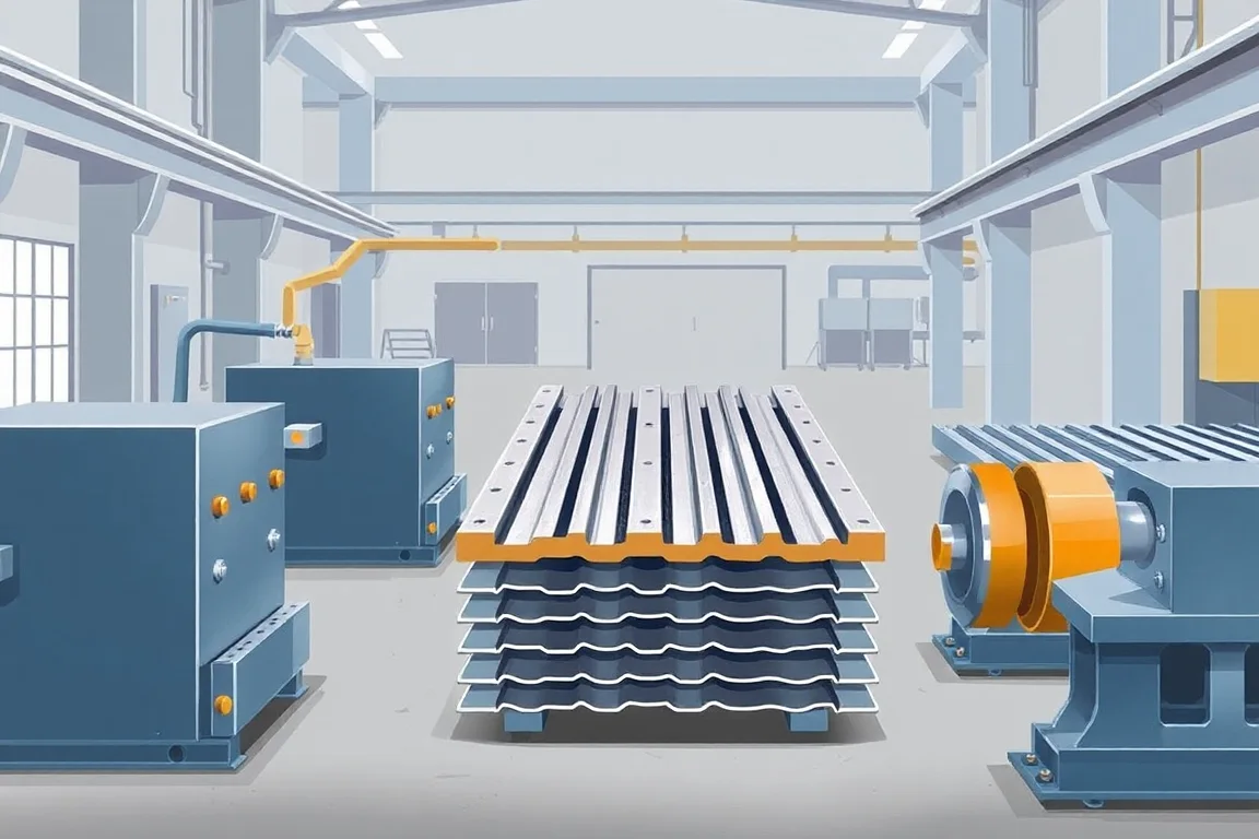
A floor deck roll forming line turns steel coil into the specified ribbed deck profile, with its side edges, surface features and cut lengths. The output may be form deck or a profile designed for a composite floor system. Those roles must be established before equipment is specified, because similar-looking sheets do not necessarily perform the same structural function.
Identify the deck product and its approved geometry
Provide the complete transverse section with rib depth, pitch, bearing flats, side laps and effective cover. Add the required embossments or other features where the design includes them. A nominal deck depth is not a complete tooling drawing.
Keep the deck's structural role explicit. Composite floor deck uses a designed interaction with concrete, while form deck and roof deck have other defined applications. The forming machine makes the approved geometry; it does not establish a load or span rating by itself.
Coil preparation supplies the specified steel
Payoff and entry equipment must handle the actual coil envelope and present material along the proposed route. State grade, thickness convention, width and coating as combinations. The line review should not rely on a thickness number separated from the material specification.
Retain coil identity with production records. A later dimensional or feature concern needs a traceable link to incoming material. This also helps distinguish a changed coil condition from a changed tooling setup during investigation.
Progressive forming develops the ribs and flutes
Successive passes move the strip toward the final section. The process must preserve the relationship between repeating ribs, bearing surfaces and terminal edges. The depth and complexity of the section make the complete development important, not only the shape of the final rolls.
Ask the supplier to explain how the proposed tooling covers the required material and profile combinations. Stand count alone is not an acceptance criterion. Representative complete sheets provide more useful evidence than a photograph of the mill.
Embossments and other features follow the deck design
Where the deck uses embossments or other defined surface features, their geometry and location belong in the equipment scope. They should not be treated as arbitrary decoration. The product's approved design determines what must be reproduced.
Identify the production stage and inspection method for each feature. A ribbed sheet with visually similar marks does not automatically reproduce the intended deck system. Manufacturing acceptance should verify the specified features without converting them into an unsupported structural claim.
Side laps establish how adjacent sheets meet
The two terminal edges can have different functions in the side-lap arrangement. Show adjoining sheets in the drawing and define the installed cover reference. Overall sheet width and effective cover are not interchangeable.
Assemble representative sheets after cutting and normal handling. Check the edge condition and intended engagement. A central rib coupon can miss a lap problem that becomes obvious only when a floor area is laid out.
Cutting must preserve the deep profile
The selected cutting arrangement should be evaluated with the actual section and required lengths. Inspect ribs, bearing areas and side edges near both ends. Local distortion can be important even when the central section meets its dimensions.
Define any further end preparation or accessory work outside the main line. Closures, pour stops and other project components may require separate operations. Do not assume a deck former supplies every item needed for a complete floor package.
Discharge and nesting protect the finished sheet
Preserve the profile and material identity on each bundle, especially where visually similar deck variants are produced. Correct labels and order references keep the accepted sheet connected to the product specification used for its manufacture.
Plan support for the longest panels and the intended stack or bundle format. Deep profiles and functional laps need handling that does not deform them. The mill's footprint alone does not describe the space required for accepted bundle production.
If nesting is part of the proposed route, demonstrate it with the actual profiles and finish. A geometry that looks correct in isolation may still be damaged by an unsuitable collection method. Inspect after that boundary rather than only at the cutoff.
Measure production as accepted deck coverage
For an illustrative order of 80 accepted sheets at 5 metres long and 0.75 metre effective cover, nominal coverage is 300 square metres. These assumed values explain the arithmetic and are not a machine capacity or structural rating.
Keep the elapsed-time boundary with the result. Include setup, cutting and bundle removal where they belong in the operational study. Rejected or damaged sheets should not remain in the accepted count merely because the strip passed through the rolls.
Follow a trial through the complete product boundary
Use approved drawings and production-intent material. Inspect the complete section, required features, length, end condition and side-lap assembly. Record the material and setup identities alongside results.
- Confirm the deck type and drawing revision.
- Verify incoming material and developed strip width.
- Measure ribs, bearing surfaces and cover references.
- Inspect specified embossments or other features.
- Check cut ends and adjoining-sheet fit.
- Inspect the accepted bundle after handling.
For a composite product, the trial establishes manufacturing conformity to its specified geometry. It does not replace the product design and performance evidence needed for the floor system. Keeping those responsibilities separate avoids treating a visually convincing sheet as a universal structural solution.
Frequently asked floor-deck process questions
Is every ribbed steel sheet composite floor deck?
No. The intended structural role and approved profile design matter. Do not infer composite performance from ribs or surface marks alone.
Can roof deck and floor deck use the same tooling?
Only where the exact required profile and equipment configuration support both products. Similar depth or appearance is not sufficient evidence.
Are embossments just an optional visual pattern?
For a design that specifies them as functional features, they must follow the approved geometry and process. Their role should not be altered casually during equipment selection.
What should be checked after stacking?
Preservation of ribs, bearing surfaces, side laps and finish, plus correct product identification. The saleable deck must remain conforming through the intended handling route.
Continue your research
- Floor Deck Roll Forming Machines
- Floor Deck Roll Forming Machine
- Roof Deck Roll Forming Machine
- B Deck Roll Forming Machine
- N Deck Roll Forming Machine
- H Deck Roll Forming Machine
- How To Choose a Floor deck roll forming machine
- Floor deck roll forming machine Price: What Affects the Cost?
- Materials and Thickness for Floor deck roll forming machine