
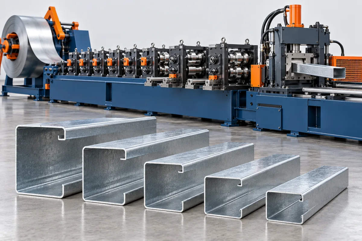
A quick change C purlin roll forming machine is designed around repeated transitions between approved C-section sizes or configurations. The C geometry keeps both flanges on the same side of the web, but web depth, flange width, lips and connection features can vary. Quick change should describe recovery of the complete finished member, not only adjustment of one dimension.
This route is worth examining when the order book contains many C members and frequent small batches. The equipment comparison should use those batches to show how tool work, setup checks and startup material affect accepted output.
Which C-section variants need to be made?
Build a matrix of web depths, flange dimensions, lips, bend radii and material combinations. Identify special returns or unequal flange requirements explicitly. A simple web-depth range can conceal substantial differences in the actual formed section.
Separate normal catalogue sizes from occasional custom work. This helps determine whether the best proposal uses adjustments, interchangeable tooling or a more dedicated arrangement. The most flexible machine is not automatically the most efficient for a stable order mix.
What does quick change include?
Ask which forming dimensions adjust and which parts must be replaced. Include entry guides, punch tooling, cutoff components and discharge supports. A short main-tool change may leave significant work elsewhere in the line.
The changeover definition should end with the first accepted new C member. Include measurement, correction and startup scrap. That result can be compared meaningfully with a fixed-profile route or another change system.
How should C-channel datums be handled?
Define web, flange and lip measurements from consistent references. Show how hole positions relate to the finished section and cut ends. A datum that is convenient on flat strip may not be sufficient for checking the installed connection.
Where the product meets cleats, tracks or other members, include representative mating references. A section can have correct overall depth while an incorrect flange angle or hole offset prevents straightforward assembly.
What production sequence should be reviewed?
Coil handling and entry preparation lead into the specified punching and forming operations. Progressive rolls develop the C web, flanges and lips. The cutting arrangement produces member lengths, followed by supported takeoff and order identification.
Ask the supplier to explain punching and cutting positions relative to forming. Their sequence can affect tool access, feature registration and end condition. The proposed route should be trialed with actual features rather than approved from a blank channel alone.
How do grade and thickness affect change recovery?
A size recipe should be associated with the material combination it was approved for. Different grades and thicknesses can change the forming result. Record the coil identity and the agreed incoming-strip requirements during trials.
Include both normal material and representative demanding combinations in the test plan. Do not combine a maximum depth from one demonstration with a maximum thickness from another and assume that the resulting combination is covered.
What should be checked after every transition?
Inspect web depth, flange widths, lip dimensions, angles and feature positions. Check straightness and twist using agreed supports. Examine local end flare or distortion separately from the general section because cutoff behavior may change with size.
- Confirm the selected drawing and material.
- Verify that all required tools changed or adjusted.
- Check the first member's hole-to-end relationships.
- Fit a representative connection where appropriate.
- Release the new order only after the agreed acceptance checks.
These checks should be practical and repeatable. A complicated inspection ritual is not the goal; the goal is a reliable method of identifying the first correct product.
How should output be evaluated for small batches?
Use a schedule with the actual batch sizes, material changes and hole patterns. Count accepted members over the complete sequence. For short batches, a modest reduction in setup work may matter more than a higher steady forming speed.
Record order sorting and bundle movement as well. Finished C sections can look similar across sizes, so identification should prevent mixing. The discharge arrangement needs to suit the smallest and largest approved members without unplanned rebuilding.
What should quotation and acceptance cover?
- The complete C-section and material matrix.
- Adjustment and replacement-tool requirements for each change.
- Punching and cutoff scope for actual connection patterns.
- Representative last-good to first-good transitions.
- Section, feature, straightness and end-quality results.
- Accepted output and startup waste for a mixed-order schedule.
If future Z production is planned, request it as a separate capability review. A quick-change C line should not be assumed to convert to Z simply because its web size is adjustable.
Frequently asked questions
Does quick change mean automatic?
Not necessarily. It can describe a convenient manual or semi-automatic arrangement. Ask for the exact tasks, required tools and demonstrated transition rather than relying on the label.
Can flange and lip dimensions vary independently?
Only within the proposed tooling design. List the required combinations and identify which adjustments or replacement components are needed for each.
Why measure end flare after a size change?
The new section can interact differently with cutting and discharge support. Local end deformation may be unacceptable even when measurements in the middle of the member are correct.
Can a C line also make plain U channels?
That requires a review of the actual U section and tooling. Omitting lips or changing flange geometry is not automatically covered by the C-profile setup.
What proves that the change system saves time?
A representative mixed-order trial measured through accepted members, including inspection and startup scrap. Main-tool movement alone does not show the complete operating benefit.
Match quick change to the C-section order book
The best configuration is the one that recovers the required C members reliably across actual batches. A clear size matrix and whole-transition trial make that result visible before the equipment decision is made.

Continue your research
- Purlin Roll Forming Machines
- C Purlin Roll Forming Machine
- Z Purlin Roll Forming Machine
- 80-300mm CZ Purlin Roll Forming Machine
- 100-400mm CZ Purlin Roll Forming Machine
- Automatic Size Change CZ Purlin Machine
- How Purlin roll forming machine Works
- How To Choose a Purlin roll forming machine
- Purlin roll forming machine Price: What Affects the Cost?
Configuration & specification inputs
Match the configuration to your section drawing, material and production requirements.
| Parameter | Requirement / confirmation needed |
|---|---|
| Profile geometry | Controlled C-section matrix with web, same-side flanges, lips and specified connections. |
| Material | Approved purlin steel grades and coatings paired with each C member. |
| Thickness & grade | Section-specific thickness and material combinations with traceable trial inputs. |
| Process route | Coil preparation, punching, adjustable or exchangeable C tooling, cutting and order identification. |
| Cutting | Required lengths with controlled local flare and correct hole-to-end registration after changes. |
| Output | Accepted C-member batches including adjustment, inspection and startup material. |
| Electrical supply | Utilities for forming, feature operations, cutoff and selected discharge equipment. |
| Acceptance | Web, flanges, lips, angles, holes, straightness and connection fit after representative changes. |