
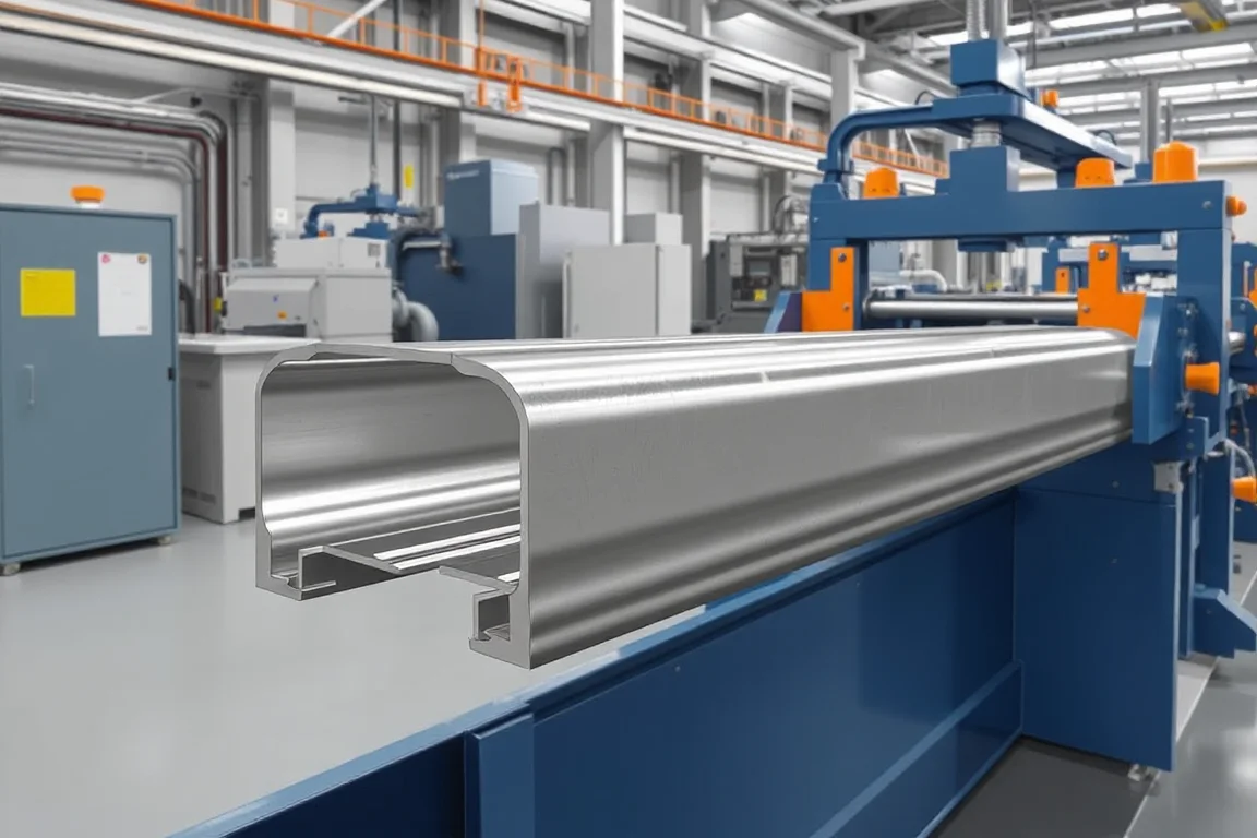
What an automotive seat rail roll forming machine actually produces
A seat rail is not simply a channel. It is a structural and kinematic component that allows the seat to slide, lock and transfer load into the vehicle floor. The roll forming machine produces the rail profile itself—often a pair of mating sections—by progressively bending a strip of steel into a shape that mates with its counterpart and receives holes, slots and joining features. The machine may also perform in-line piercing, notching and cutoff, and may integrate joining operations such as welding or clinching if the part design calls for them.
The distinction between the forming machine and the finished seat rail assembly matters because the machine’s scope ends where assembly and certification begin. A roll forming line can produce a dimensionally consistent profile, but it does not by itself validate the sliding feel, locking strength or crash performance of the assembled rail pair. Those attributes depend on the entire sliding assembly—both rails, any bearings or sliders, the locking mechanism and the attachment to the seat structure.
Why seat rail profiles are more than a channel
Automotive seat rails usually have at least one moving interface: the upper rail (attached to the seat) slides relative to the lower rail (attached to the floor). The profile must therefore control clearance and contact in a way that permits smooth motion without excessive play. The geometry often includes return flanges, track surfaces and features that retain or guide rolling elements or sliding blocks. Holes and slots locate the locking mechanism, mounting brackets and wiring clips.
Because these features interact, a feasibility review must consider the whole sliding assembly, not just a similar-looking channel. A profile that forms acceptably in isolation may fail to meet functional requirements once paired with its mate or once the seat is assembled. The forming process must support the relationship between features—hole positions relative to bend radii, flange flatness relative to sliding surfaces—rather than only the profile outline.
Drawing and material inputs that shape the process
The starting point is a controlled part drawing. The drawing defines section geometry, datum scheme, hole patterns, joining flanges and assembly interfaces. Datums are particularly important because they establish how the part will be measured and how it will be located in downstream assembly and welding fixtures. Without a clear datum scheme, inspection results cannot be compared meaningfully.
Material specification also drives the process. Seat rails are commonly made from drawing-specified automotive steel, which may be coated or uncoated, and may range from mild to higher-strength grades. The buyer specifies base-metal thickness and grade, but the operating range of the machine requires supplier verification. Higher-strength material can require different bend radii, pass development and springback compensation. Springback—the tendency of metal to partially return to its original shape after bending—must be compensated in the roll tooling, and the compensation that works for one grade may not suit another.
Production route: from coil to verified rail
A typical production route for seat rail profiles is traceable coil feed, precision forming, feature and cut operations, joining, and dimensional verification. Each stage has a purpose and a boundary:
- Traceable coil feed: The coil is identified and tracked so that material grade and heat can be linked to finished parts. This supports problem solving and potential recall traceability.
- Precision forming: The strip passes through a series of roll stands that progressively bend it into the desired section. The number of passes, roll design and lubrication strategy depend on the profile complexity and material.
- Feature and cut operations: In-line piercing, notching and cut-off create holes, slots and the final part length. The cut-off must be supported by the profile to avoid distortion or burrs.
- Joining: If the rail design requires welded or clinched subcomponents, these operations may be integrated into the line or performed as a secondary step.
- Dimensional verification: First-off and steady-production samples are checked against the drawing using agreed datums and gauges.
This route is not a universal recipe. Some seat rail designs may omit joining or may require additional operations such as sweeping (a secondary bending or forming step) or the insertion of fasteners. The appropriate route depends on the specific part and its assembly strategy.
Cutting and end-forming considerations
Cut-off is often underestimated in seat rail production. The cut must be profile-supported so that the rail section does not collapse or distort as the blade passes through. The cut length must meet the drawing tolerance, and the cut face quality matters if it will be visible or if it affects assembly. In some cases, secondary operations such as deburring or end-forming are needed.
The machine builder should confirm whether the cutoff is supported by an internal mandrel or by external clamps, and whether any secondary operations are required. This is not a matter of asking for a supplier’s standard answer; it is a matter of matching the cut-off method to the profile stiffness, material thickness and end-use requirements.
Assembly boundaries: what the roll forming machine does not do
It is important to separate the production of the rail profile from the assembly of the sliding rail system. The roll forming machine produces a single rail (or possibly both rails if the line is configured to run two profiles). The assembly of the upper and lower rail, the installation of sliders or bearings, the attachment of the locking mechanism and the final functional check are separate operations. These may be done by the seat manufacturer or by a tier-one supplier.
Conflating forming with assembly can lead to unrealistic expectations. A roll forming machine cannot guarantee that the assembled rail will slide within a specified force range or that the locking mechanism will engage reliably. Those are system-level properties that depend on the cumulative tolerances of both rails, the sliding elements and the assembly fixture. The machine’s role is to produce profiles that meet their individual specifications, which in turn contribute to the assembly’s performance.
Application-specific inspection and acceptance
Inspection for seat rails must be tied to the function of the rail and the assembly. Section accuracy alone cannot establish vehicle-seat or restraint-system performance, but it is a necessary input. A practical inspection plan includes:
- Verification of key dimensions against the drawing, using the agreed datums. This may include profile height, width, flange lengths and bend angles.
- Position and size of holes and slots, especially those that locate the locking mechanism or mounting brackets.
- Straightness and twist of the rail, which affect sliding fit and assembly.
- Cut-off length and end quality.
- For joined components, check weld or clinch integrity per the applicable specification.
Acceptance criteria should be agreed before tooling approval. This means the buyer and machine builder should define how mating rails, feature positions and finished assemblies are evaluated, and record the process changes that require review. For example, a change in material grade or thickness may require re-validation of forming and downstream joining. The inspection method—whether using dedicated gauges, CMM or functional fixtures—should also be agreed, because different methods can yield different results.
Comparing production alternatives
When considering how to produce seat rails, several routes exist, each with trade-offs:
- Roll forming: Suitable for long, consistent profiles with integrated features. Tooling cost is higher, but cycle times can be short and material utilization good. Best for high-volume production where the profile is stable.
- Stamping and bending: May be used for shorter rails or where the profile has complex local features that are difficult to roll form. Tooling can be simpler, but cycle times may be longer and material handling more complex.
- Press braking: Often used for low-volume or prototype rails. Flexible but slow, with more manual handling and less consistency.
- Extrusion (aluminum): An alternative for some lightweight seat structures, but requires different joining methods and may not match the stiffness or crash behavior of steel.
The choice depends on volume, material, profile complexity and the required mechanical properties. Roll forming is often selected for steel seat rails because it can produce a strong, stiff section efficiently, but it is not the only option. The decision should be based on a feasibility review that considers the entire sliding assembly and the validation plan.
Practical checklist before approving a production line
Before committing to a seat rail roll forming machine, work through the following checklist with the machine builder:
- Run the agreed material and profile, not an easier demonstration substitute.
- Inspect first-off pieces and a representative steady-production sample with the agreed gauges.
- Record changeover steps, setup scrap, punching and unloading time.
- Compare the written equipment scope with all secondary operations needed for a finished part.
- Clarify who is responsible for part validation—forming trials, dimensional reports, material certificates and any functional testing.
- Confirm that the electrical supply (voltage, frequency, phase) matches the buyer’s facility and that the installed power is documented in a confirmed equipment schedule.
- Define the acceptance criteria for the profile and, if applicable, for any joined subassemblies.
- Agree on traceability requirements from coil to finished part.
This checklist is not a substitute for a detailed feasibility study, but it helps separate production hardware from part-validation responsibilities and highlights where cost and risk may lie.
FAQ: specific questions about seat rail roll forming
Can one roll forming machine produce both the upper and lower rails of a seat slide?
It is possible if the two profiles are similar enough in width and forming sequence, but it is not automatic. The upper and lower rails often have different cross-sections, material thicknesses or feature patterns. A single line might run both if the tooling is designed for quick changeover and the pass line can accommodate both profiles. Otherwise, two separate lines or a dedicated line for each rail may be more practical. The decision should be based on the specific drawings and production volumes.
How do I know if my seat rail profile is feasible for roll forming?
Feasibility depends on the bend radii, the number of bends, the material grade and thickness, and the presence of features such as holes and notches. A profile with very tight bends or deep flanges may be difficult to form without cracking or excessive springback. Roll forming simulation or trial runs can help assess feasibility. The machine builder should review the drawing and propose a pass schedule, but the buyer should require evidence—such as simulation results or trial parts—before approving tooling.
What should be included in the acceptance criteria for a seat rail?
Acceptance criteria should cover dimensional and functional requirements. Dimensionally, they should define the datums, the key dimensions to be checked, and the tolerances. Functionally, they may include sliding force, locking strength and durability, but these are assembly-level properties. For the roll formed profile, acceptance typically includes section dimensions, hole positions, straightness, twist, cut length and surface condition. The criteria should be agreed in writing before tooling approval and should include the measurement method.
Why is material traceability important for seat rail production?
Material traceability links the finished rail to the coil from which it was made. If a problem is found in the field or during assembly, traceability allows the manufacturer to identify the affected production lot and take appropriate action. It also supports quality control by allowing correlation of forming issues with specific material heats. Traceability is typically achieved by recording coil identification and maintaining a link to the parts produced from that coil.
What downstream operations might be needed after roll forming a seat rail?
Downstream operations can include deburring, welding or clinching of brackets, insertion of fasteners, and washing or coating. Some of these may be integrated into the roll forming line, while others are performed offline. The need for downstream operations should be identified during the feasibility review so that the equipment scope and cycle time calculations reflect the complete production process, not just the forming machine.
How does the choice of steel grade affect the roll forming process?
Higher-strength steels tend to have greater springback and may require more forming passes, different roll materials or additional compensation. They may also be more sensitive to edge cracking, so bend radii may need to be increased. The roll forming machine must be capable of handling the specified grade and thickness range. The buyer should provide the grade and thickness, and the machine builder should confirm the operating range based on tooling design and trial results. A machine that forms mild steel may not perform the same way with high-strength steel.

Continue your research
- Automotive Roll Forming Machines
- Automotive Bumper Beam Roll Forming Machine
- Automotive Door Beam Roll Forming Machine
- Automotive Window Guide Channel Roll Forming Machine
- Heavy Truck Side Member Roll Forming Machine
- Trailer Side Wall Post Roll Forming Machine
- How Automotive roll forming machine Works
- How To Choose a Automotive roll forming machine
- Automotive roll forming machine Price: What Affects the Cost?
Configuration & specification inputs
Match the configuration to your section drawing, material and production requirements.
| Parameter | Requirement / confirmation needed |
|---|---|
| Profile geometry | Seat rails have mating and motion interfaces that may demand specialized forming and subsequent operations. A feasibility review must cover the entire sliding assembly, not just a similar-looking channel. |
| Material | Drawing-specified automotive steel or other validated alloy |
| Thickness & grade | Buyer to specify base-metal thickness and grade; operating range requires supplier verification. |
| Process route | Traceable coil feed → precision forming → feature/cut operations → joining → dimensional verification |
| Cutting | Confirm profile-supported cutoff, cut lengths, end quality and any secondary operations. |
| Output | Define accepted output per shift with the actual profile and material. |
| Electrical supply | Buyer to state voltage / frequency / phase. Installed power requires a confirmed equipment schedule. |
| Acceptance | Define how mating rails, feature positions and finished assemblies are evaluated. Record the process changes that require review. Section accuracy alone cannot establish vehicle-seat or restraint-system performance. |