
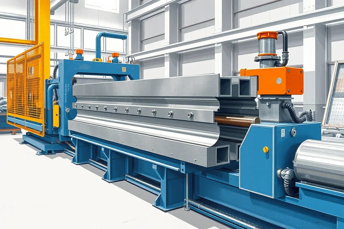
A guardrail spacer block roll forming machine enquiry concerns the specified formed-metal component between a barrier rail and its post. The spacer establishes a defined offset and connection relationship in the selected system. Its shape, material, holes and orientation must follow the controlled barrier drawing.
Not every spacer block is a roll-formed product. Some designs use other materials or fabrication methods, and a metal design may require punching, bending, joining or end finishing beyond longitudinal forming. The first task is to define the actual spacer and choose an appropriate manufacturing route.
What spacer construction is required?
Provide the complete component drawing, including open or closed form, dimensions, returns and any seam or joint. Show the connection to both the post and rail. A front view alone may hide the geometry that establishes the offset.
Identify whether the part is cut from a repeating roll-formed section or made through another fabrication sequence. The equipment proposal should explain why the proposed route suits the component and expected volume rather than assume roll forming is always the answer.
Which interfaces determine the finished shape?
The post-facing and rail-facing surfaces must meet the intended components in the specified orientation. Hole positions, offsets and contact areas need clear datums. Use actual mating references in the review.
Do not change the spacer dimensions to suit an available roll set without the relevant system-design approval. This is a barrier component, and its relationship to the other parts is part of the controlled product.
What should the feature and end schedule include?
- Hole or slot shapes and directions.
- Positions relative to the two connection faces.
- Cut length and end geometry.
- Any closure, joining or secondary bend.
- Orientation and part identification.
For short spacers, feature-to-end relationships can be a major part of the production requirement. The trial should use the actual short component rather than a long uncut sample of the underlying section.
How can a roll-formed spacer route work?
Where the design is suitable, strip is prepared and featured, then progressively formed into the repeating cross-section. Cutting separates individual spacer lengths. Additional joining or finishing operations complete the part where the drawing requires them.
Ask which operations are integrated and which occur at a separate station. A machine that makes the long section may not deliver a complete spacer. The quotation should identify the output condition at every handoff.
Why does short-piece handling need attention?
Spacers can be much shorter than guardrail beams or posts. The cutoff and transfer system must control those pieces without damaging connection faces or allowing parts to collide unpredictably. The actual geometry should be demonstrated in the proposed takeoff.
Inspect the first and last features on each cut component. Cutting registration, burr condition and local distortion can govern whether the spacer bolts into its intended assembly. Count accepted complete parts, not just cut events.
How should material and coating be specified?
Use the approved steel grade, base-metal thickness and corrosion-protection route. Identify whether the part begins with coated strip or receives coating after fabrication. Any joining and coating sequence needs to be defined with the responsible process suppliers.
Retain material and batch identity through secondary operations. A spacer that passes geometry checks before coating should still receive the required final inspection under the agreed process plan. Do not treat coating as a substitute for correct forming.
Can one line make several spacer designs?
Different offsets, connection faces or closed shapes can need substantially different tools. List each component separately and identify shared operations. A length change within one section is a different requirement from a new spacer construction.
Measure changeover through an accepted complete spacer fitted to its intended post and rail references. Include punch tools, cutting registration, joining fixtures and inspection where applicable. This reveals the true cost of serving several barrier systems.
What should the acceptance assembly show?
- Confirm the controlled spacer drawing and material.
- Measure offset, faces, section and cut length.
- Inspect holes, ends and any joined features.
- Fit the spacer to the specified post and rail references.
- Verify orientation and fastener access.
- Check condition after coating and handling within the agreed scope.
- Record accepted complete parts and secondary work.
The assembly check establishes component fit. It does not replace the applicable qualification of the complete roadside barrier system or authorize a new spacer substitution.
Frequently asked questions
Can every guardrail spacer be roll formed?
No. Material, geometry and volume determine the suitable route. Some components need pressing, bending, joining or another process, so start with the actual drawing.
Does a roll former deliver a finished spacer?
Only if all required cutting, features and secondary operations are included. Identify the exact output condition instead of assuming a formed section is the complete part.
Can spacer offset be changed freely?
No. It belongs to the controlled barrier-system component design. Any change needs the relevant approval, not just a convenient machine adjustment.
Why use both rail and post references in a trial?
The spacer connects two interfaces. Checking one face alone can miss orientation, offset or access problems at the other side.
What should a buyer provide?
Send the complete spacer drawing, material and coating route, mating components, required volume and variants. Include any joining or secondary operation already planned elsewhere.
Choose the process around the complete spacer
A useful spacer-machine proposal starts with the barrier component and its two interfaces. That clarifies whether roll forming is appropriate and ensures acceptance covers the finished part rather than only its repeating section.

Continue your research
- Guardrail & Crash Barrier Roll Forming Machines
- W Beam Guardrail Roll Forming Machine
- Thrie Beam Guardrail Roll Forming Machine
- Guardrail C Post Roll Forming Machine
- Guardrail Sigma Post Roll Forming Machine
- Guardrail U Post Roll Forming Machine
- How Guardrail roll forming machine Works
- How To Choose a Guardrail roll forming machine
- Guardrail roll forming machine Price: What Affects the Cost?
Configuration & specification inputs
Match the configuration to your section drawing, material and production requirements.
| Parameter | Requirement / confirmation needed |
|---|---|
| Profile geometry | Approved metal spacer construction with controlled offset, post face, rail face and any closure or joint. |
| Material | Barrier-specified material and coating route for the actual spacer design. |
| Thickness & grade | Component-controlled thickness assessed with forming, features and secondary operations. |
| Process route | Suitable blank or coil preparation, features, section forming where appropriate, cutting and defined completion steps. |
| Cutting | Short spacer lengths and end condition preserving both connection interfaces. |
| Output | Accepted complete spacers with secondary operations and handling explicitly included or separated. |
| Electrical supply | Utilities for the selected forming or fabrication route and its finishing stations. |
| Acceptance | Offset, faces, holes, ends, joined features, orientation and fit to intended rail and post references. |