
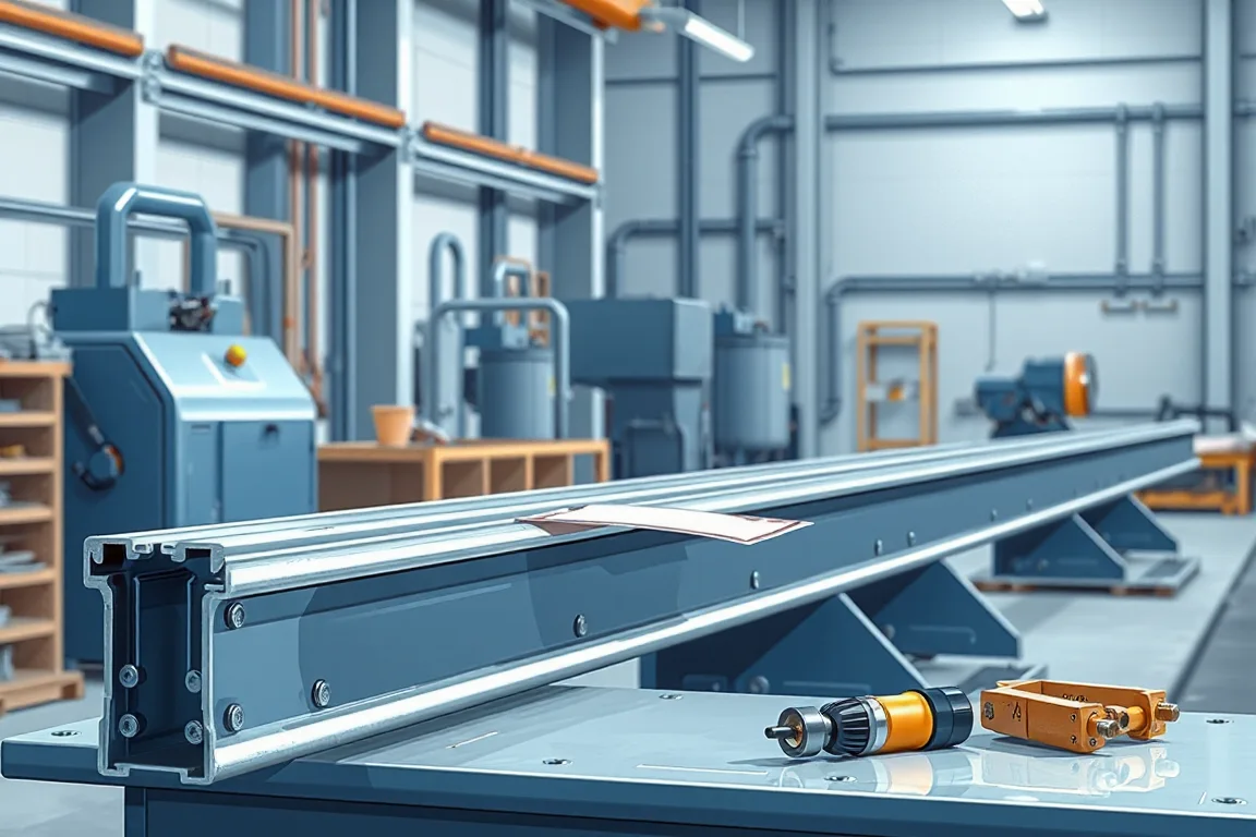
Choosing a guardrail roll forming machine is a component manufacturing decision, not a barrier-system decision. A roadside barrier is a tested assembly of beams, posts, spacers and connections. Roll forming produces one or more of those components to a drawing; it does not establish crashworthiness, nor does it approve an installation. The practical starting point is therefore the component drawing and the procurement specification that governs it, including end laps, splice-hole patterns and fixing slots. From that drawing you can derive the forming route, the tooling scope and the measurements that will decide acceptance.
This guide explains the sequence inside a line, the decisions that distinguish one configuration from another, how quote scopes differ, and how to compare alternatives without relying on unverified output claims.
Start With the Approved Component Drawing, Not the Machine
The drawing fixes the wave geometry, the number and position of waves, the bolt-slot pattern, lap orientation and post connection geometry. Those features, not the machine model name, determine whether a proposed line can produce an acceptable part. Two suppliers may both offer a line for a beam profile while quoting different tooling, different punch positions and different cutoff arrangements; the drawing is what makes their offers comparable.
Component production should also be separated from assembly, certification and in-service performance. A line that forms and punches beams correctly still leaves coating sequence, post fabrication, spacer production, fasteners and installation approval to other processes and other evidence. Treat dimensional acceptance of the formed component as one milestone, and system-level qualification as a separate matter outside the machine scope.
How a Guardrail Roll Forming Line Works: Sequence and Interfaces
A typical line follows a sequence: material is paid off and leveled, holes or slots are punched, the strip is progressively formed through a series of roll stands, the beam is cut to length, and the part moves to coating or assembly operations as specified. Each step has an interface that matters.
Leveling establishes flat strip entering the punches, so it affects hole position consistency. Punching must reference the splice datums so that holes align across laps. Forming then develops the wave geometry; if the punch pattern is set before forming, the subsequent deformation must not distort hole position or slot shape beyond drawing tolerance. Cutoff must be profile-supported so the end is square enough for lap and splice requirements. Coating sequence, whether before or after forming and punching, must be agreed because it changes handling, hole edge condition and downstream operations.
The line does not work as isolated stations. Leveling, punching, forming and cutoff interact, and a change in one area can move the finished dimensions in another. This is why acceptance measurements should be agreed before tooling is committed.
Profile Decisions: Beam Waves, Splice Datums and Lap Fit
W beam and two-wave beam describe the same broad geometry, and thrie beam and three-wave beam likewise overlap. Use the approved drawing to identify genuine differences rather than relying on a familiar name. The decisions that matter are the wave depth and spacing, the location of splice holes relative to the wave, and how the lap sits when two beams are joined.
Lap orientation deserves attention during selection. The overlap may be designed one way along the line, and the punch tooling must place the fixing slots so that the lap closes correctly in service. A machine that produces the right wave but the wrong slot position relative to the lap is not producing an acceptable component, even if the beam looks correct in profile.
Post connection geometry is a separate interface. It defines where the beam is fixed to posts or spacers, and it constrains the hole pattern and the length and end condition of the beam. If the drawing shows connection features that are not produced on the forming line, the quote must state which operations are excluded.
Material and Thickness Decisions
The buyer specifies the base-metal thickness and grade that the barrier system requires. Those values come from the approved drawing and procurement specification, not from a forming machine brochure. The operating range of any proposed line requires supplier verification against that specific material envelope.
Material decisions also influence coating. Whether the product is formed from pre-coated coil or coated after forming changes the forming behavior, the condition of cut and punched edges, and the handling between stations. The coating sequence must be agreed early because it affects both the process route and the acceptance criteria. A forming line that performs as intended with one coating state may need different handling with another, and that difference should be examined during selection rather than discovered in production.
Punching, Tooling and Forming Design Trade-offs
Punch tooling must reference the splice datums. That requirement drives several choices: the number and arrangement of punches, whether slots and rounds are produced in the same tool, and how the punch station is positioned relative to the forming stands. A tool designed for one fixing pattern generally does not produce a different pattern without modification.
Roller and forming design also involves trade-offs. More forming stands can distribute strain more gradually, which may help with thicker or higher-strength material, but it increases line length, tooling cost and changeover complexity. Fewer stands may reduce cost and footprint while demanding more from each pass. The right balance depends on the section family, the material envelope and the intended product mix. If the same line is expected to run more than one section, the changeover method becomes part of the comparison: how tooling is exchanged, how punch positions are reset, and how the changeover is demonstrated.
Cutoff, Length Control and Secondary Operations
Confirm that the cutoff is profile-supported for the intended beam. Cutting a formed section without adequate support can deform the end, which then affects lap fit and splice alignment. The cut length capability should be stated against the intended product lengths, and the end quality should be defined in measurable terms such as squareness and freedom from distortion.
Secondary operations matter as much as the main stations. If the drawing requires embossing, notching, marking, hole edge treatment or additional punching after forming, those operations must appear in the quote scope with the equipment that performs them. A line that forms and cuts the beam but leaves a required operation to separate equipment is not a complete solution for that drawing.
Output: Define Accepted Output, Not Machine Claims
There is no substitute for defining output in terms of accepted parts. Rather than accepting a headline rate, specify the output per shift for the actual profile and material, with acceptance criteria applied. A line may run quickly for a short interval but lose parts to dimensional nonconformance, stop for coil changes or require frequent adjustment. Accepted output per shift, measured against the agreed inspection, is the figure that reflects production value.
Output also interacts with the product mix. A line dedicated to one beam section behaves differently from one that changes between sections or between punched patterns. If the production plan includes more than one product, the comparison should reflect the time and scrap associated with changeover, not only steady running.
Power, Services and Site Interfaces
The buyer states the voltage, frequency and phase available at the installation site. Installed power requires a confirmed equipment schedule covering every motor, heater and control on the line, including any equipment outside the main machine that the process depends on. Services such as compressed air, cooling, dust or fume extraction and foundation requirements should be listed as included or excluded so the site preparation is not underestimated.
Comparing Forming Routes and Alternatives
Several routes can produce a guardrail beam component, and they differ in flexibility, tooling cost and acceptance risk. A dedicated line configured for one profile and one punch pattern tends to give the most consistent dimensional result for that product, but it is less adaptable if the product mix changes. A line with interchangeable tooling and adjustable punch stations can cover more sections, at the cost of longer changeover and more setup discipline. Purchasing formed beams or subcontracting the operation shifts capital and tooling risk away but gives up control over delivery and dimensional verification.
A used or rebuilt line may reduce initial capital, but the tooling condition, control system and safety devices determine whether it can hold the required tolerances. The comparison should be made on the same drawing revision and material envelope so that like is compared with like. A machine that appears less expensive may exclude punching, cutoff support or coating handling that the drawing requires.
What a Meaningful Demonstration Looks Like
A demonstration should use the intended profile and material, or a close representative. Inspect wave geometry, splice-hole position, lap fit and beam length. Check that holes align across a simulated lap and that the cut end supports that lap. Record the measurements that define acceptance, and separate them from system crash-testing and installation approval, which are not established by a forming demonstration.
The demonstration is also an opportunity to observe changeover if the product mix includes more than one section, and to see how the line handles a coil change or a restart. Keep the focus on dimensional evidence rather than claims.
Practical Selection Checklist
- Use the approved drawing revision and the applicable procurement specification as the basis for every offer.
- Define the profile family, wave geometry, splice datums, lap orientation and post connection features in the drawing package.
- State the base-metal thickness and grade, and require supplier verification of the operating range for that envelope.
- Agree the coating sequence and identify which operations occur before and after forming and punching.
- Confirm that punch tooling references the splice datums and produces the required slot and hole pattern.
- Confirm cutoff support, cut lengths and end quality requirements.
- List all secondary operations and the equipment that performs them.
- State site voltage, frequency, phase and services, and request a complete equipment schedule for installed power.
- Define accepted output per shift against the actual profile and material, with acceptance criteria applied.
- Agree acceptance measurements before committing to tooling, including wave geometry, hole position, lap fit and length.
- Keep component dimensional acceptance separate from crash-testing and installation approval.
- Compare the same material, section family and finished-part scope across all offers, marking items as required, included or excluded.
Frequently Asked Questions
Can one guardrail roll forming line make beams, posts and spacers?
Not necessarily. Posts, beam sections and spacer blocks may need different processes, and a single line is unlikely to cover all of them without separate tooling or separate machines. The drawing package for each component should be examined separately, and the quote should state which components are produced on the proposed line and which are excluded.
How do I compare offers when the machine descriptions use different terms?
Ask each supplier to answer against the same drawing revision and material envelope. Require them to state, for each required feature, whether it is included, excluded or proposed as a future option. This makes the offers comparable even when the marketing descriptions differ. If production depends on equipment outside the quote, include that equipment in the comparison.
What should be measured to accept a formed beam?
Inspect wave geometry, splice-hole position, lap fit and beam length. These measurements should be agreed before tooling is committed, and they should be taken on the intended material. Keep this dimensional acceptance separate from system crash-testing and installation approval, which fall outside the machine scope.
How should I think about output when no verified model rating is available?
Define accepted output per shift with the actual profile and material, and apply the acceptance criteria to the count. This accounts for dimensional losses, coil changes and adjustment time. A headline rate that is not tied to acceptance is not a reliable basis for comparison.
What does the power and services part of the quote need to cover?
The buyer states voltage, frequency and phase. The supplier should provide a confirmed equipment schedule showing installed power for all motors, heaters and controls, including equipment outside the main machine. Site services, foundations and any required extraction should be listed as included or excluded so the installation scope is clear.
How do I handle changes in profile or punch pattern after the line is ordered?
Profile and punch pattern changes generally require tooling modification or replacement, so they should be raised before tooling is committed. If the production plan includes multiple sections, request a changeover demonstration for the intended product mix during selection. Agreeing acceptance measurements early reduces the risk that a later change invalidates the tooling design.
Continue your research
- Guardrail & Crash Barrier Roll Forming Machines
- W Beam Guardrail Roll Forming Machine
- Thrie Beam Guardrail Roll Forming Machine
- Guardrail C Post Roll Forming Machine
- Guardrail Sigma Post Roll Forming Machine
- Guardrail U Post Roll Forming Machine
- How Guardrail roll forming machine Works
- Guardrail roll forming machine Price: What Affects the Cost?
- Materials and Thickness for Guardrail roll forming machine