
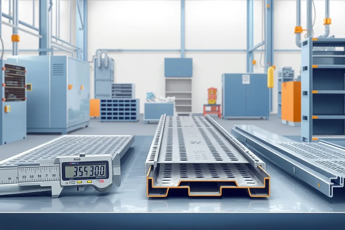
The material thickness question is really a specification question. A cable tray roll forming machine does not have one universal thickness capability; it has an operating envelope defined by the strip grade, the base-metal thickness, the coating, the tray profile, the number of forming stations and the way the cutoff is built. Buyers who specify only a gauge number or a vague range create avoidable risk, because the same nominal thickness in a harder or softer material behaves differently through the rolls. The practical answer is to define the material as a written combination of grade, strength range, base-metal thickness, permitted thickness variation and coating, then confirm that the proposed machine is intended to run that combination across the full profile range.
Why thickness is a combination, not a single number
Thickness interacts with yield strength, ductility, coating type and coating weight. A strip that springs back more after bending needs different roll geometry and different station spacing than a more formable strip of the same nominal thickness. Coating adds surface condition as well: galvanized, pre-coated and stainless surfaces each behave differently against forming rolls, and the exposed face may need protection from marking. This is why a machine demonstrated on one grade at one thickness has not thereby demonstrated capability for every harder, softer, thinner or thicker material. Supported combinations should be listed in writing rather than inferred from unrelated maximum values.
Thickness also sets the scale of the whole line. Heavier strip demands more forming torque, stiffer shafts, larger bearings, stronger stands and a cutoff able to shear the section cleanly. Lighter strip raises different problems: buckling, oil-canning across the base, twist in the side walls and difficulty holding a consistent return edge. Neither direction is simply "easier".
How thickness moves through the forming sequence
A typical line runs payoff, leveling, perforation or punching, side forming, cutoff and then cover or assembly checks. Each interface passes constraints to the next.
- The payoff must feed the strip without inducing a coil set that leveling cannot remove, because residual curvature appears later as bow or twist.
- Leveling sets flatness and relieves internal stress; a strip that enters forming with uneven stress will not form symmetrically.
- Perforation or punching removes material and locally changes stiffness. Holes near a bend line reduce the section's resistance to distortion.
- Side forming creates the base, side walls and return edges. The sequence of edge returns relative to punching matters, because forming a return close to a hole field can pull the holes out of position or open them.
- Cutoff must suit the formed profile. A cutoff that works on a shallow return may crush or distort a deeper one.
Thickness affects every one of these steps, so the operating envelope should be expressed per profile, not as a single line-wide figure.
Base-metal thickness versus coating and gauge labels
Gauge numbers are ambiguous because they do not state the standard or whether the figure refers to base metal or coated thickness. Buyers should specify base-metal thickness and permitted variation directly, and state the coating separately as a corrosion requirement. For a pre-coated or film-protected strip, say so explicitly, because the exposed face and surface finish influence handling, roll contact and any later finishing step. Corrosion requirements belong in the product specification; the machine specification should reflect the material that will actually be bought.
How profile geometry and thickness work together
Base width, side height and return edge geometry are not independent of thickness. A deeper side wall on thinner material is more prone to twist; a wide base on heavier material needs more forming force and stiffer support. Perforation pitch and pattern also interact with both: a dense pattern in thin strip reduces stiffness noticeably, while the same pattern in heavier strip changes punch loads and tool wear.
Define the finished part first, including any cover and whether adjustable widths are required. Only then can machine layout, forming stations, perforation tooling and cutoff be matched to the task. A ladder-type system should not be treated as a perforated tray with larger openings; rail forming, rung production and assembly may sit outside the rail line altogether.
How to compare machine alternatives
Compare proposals on the supported combination, not headline figures. A machine offered with wide thickness flexibility may achieve it only by accepting looser tolerances or slower running; a narrower machine may hold tighter geometry. Ask how widths are adjusted, how perforation pitch changes, and whether the cutoff supports every size in the intended range. Consider these tradeoffs:
- Fixed-width tooling versus adjustable-width arrangements: fixed tooling can hold geometry more consistently but limits variety; adjustable arrangements add flexibility but require verification at each setting.
- Integrated perforation versus separate pre-punched coil: integrated punching gives scheduling control but adds tooling and setup; pre-punched coil simplifies the line but constrains material sourcing.
- In-line cutoff versus secondary operations: in-line cutoff shortens handling but must suit the deepest and widest profile offered.
- Single-material focus versus multi-material claims: focused tooling tends to be more repeatable, while multi-material capability needs explicit supported combinations.
Burr, edge condition and cable contact
Cutoff and perforation both create edges that can contact cable insulation. Burr condition and edge protection therefore belong in acceptance, not as an afterthought. Inspect around holes after forming, because forming can distort a punched edge. Where later finishing is planned, say so, because a finish operation may or may not address an edge condition that should have been controlled at the machine.
Acceptance checks that reflect thickness
Acceptance should confirm the geometry that thickness affects: base width, side height, return edge form, overall straightness and the condition of perforated edges. Cover engagement should be checked on the finished part, since cover fit depends on the formed return. Load rating and electrical continuity depend on the complete installed system and its own verification, not on the forming line alone, so they should not be presented as machine acceptance criteria.
Practical specification checklist
- State grade and strength range separately from base-metal thickness.
- State base-metal thickness and permitted variation, with the standard named.
- State coating type, coating requirement and whether the face is pre-coated or film-protected.
- List every profile to be produced, with base width, side height and return edge.
- Describe perforation pattern, pitch and position relative to bends and returns.
- Specify the finish and exposed face, plus any later finishing operation.
- Define accepted output per shift using the actual profile and material, not a generic figure.
- Provide representative samples from the intended coil supplier for evaluation.
- State voltage, frequency and phase, and request a confirmed equipment schedule for installed power.
- Confirm which profile, thickness, grade and coating combinations are supported in writing.
Where thickness issues show up in service
Thickness-related problems often appear as distortion rather than as a failure of the machine. Twist, bow, uneven side height, open or closed return edges, hole distortion near bends and inconsistent cover fit all trace back to the interaction between material, tooling and forming sequence. Documenting the intended thickness range and grade makes diagnosis faster, because it separates a material change from a setup or tooling change.
FAQ
Can one machine run several thicknesses?
Often yes, but only within a stated envelope. What matters is which grade, thickness and profile combinations are supported together. A machine may accept a range of thicknesses in one material while supporting a narrower range in a harder grade, because forming loads and springback differ. Request supported combinations rather than a minimum and maximum presented in isolation.
Why is gauge not enough to specify the strip?
Gauge labels vary by standard and may refer to base metal or coated thickness. Two strips described with the same gauge number can differ in actual base-metal thickness and coating, producing different forming behaviour. Specify base-metal thickness with permitted variation and name the standard rather than relying on a gauge shorthand.
How does thickness affect perforation and cutoff?
Punching force, tool wear and the tendency of holes to distort near a bend all change with thickness and grade. Cutoff must shear the formed section without crushing the return edge or leaving an unacceptable burr. Deeper or wider profiles place more demand on the cutoff, which is why the cutoff should be confirmed for every size in the intended range.
Does a heavier strip make forming easier?
Not necessarily. Heavier strip resists buckling and oil-canning but increases forming torque and tool loads, and it can be less forgiving of roll alignment. Thinner strip forms with less force but is more prone to twist and to waviness across the base. Each direction carries its own control methods and acceptance concerns.
What should be checked on the formed tray?
Check base width, side height, return edge form, straightness and burr condition, and inspect around perforations after forming because forming can change a punched edge. Confirm cover engagement on the finished part. Load rating and electrical continuity are properties of the installed system and should be verified separately.
How should a buyer compare proposals fairly?
Compare on the supported profile, material and thickness combinations, the width and perforation changeover method, cutoff suitability and the definition of accepted output. Provide representative samples and ask how each proposal handles the tightest geometry in the range, rather than comparing unrelated maximum claims.
Continue your research
- Cable Tray Roll Forming Machines
- Cable Tray Roll Forming Machine
- Cable Ladder Roll Forming Machine
- Solid Bottom Cable Tray Roll Forming Machine
- U Channel Cable Tray Roll Forming Machine
- Cable Support Channel Roll Forming Machine
- How Cable tray roll forming machine Works
- How To Choose a Cable tray roll forming machine
- Cable tray roll forming machine Price: What Affects the Cost?