
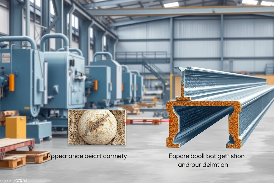
Custom profile troubleshooting should begin with the exact feature that fails, not a general instruction to adjust the rolls. A section can have acceptable overall dimensions yet show poor mating fit, a damaged return, misplaced holes or local cutoff distortion. Preserve the production context and investigate where the condition first appears.
Define and contain the defect
Identify the affected part, drawing revision, material and production interval. Separate suspect output from accepted stock and mark sample orientation. Record the last known good check so that the extent of the issue can be assessed.
Use the approved stop, isolation and inspection procedures for the equipment. Do not investigate contact points or remove material from a moving forming or cutting area. Adjustments and tool service belong to trained personnel using the required safeguards.
Verify the inspection reference
Confirm that the correct drawing, datums and measurement method are being used. Long or flexible parts can give different readings under different support conditions. Repeat the measurement consistently before treating the result as a process change.
Compare the middle and both ends of the component. Note whether the condition is continuous, periodic or confined to a local feature. That simple distinction helps separate a broad forming issue from a cutoff, feature or handling problem.
Compare the event with material and setup changes
Establish whether the condition began after a coil change, variant transition, tool service or program update. Verify material identity, thickness information and incoming strip condition. Do not assume that nominally similar coils or parts are identical.
Check the selected tools and setup references against the approved record. An incorrect combination can produce a plausible-looking section that fails a particular interface. Similar custom variants make clear tool and part identification especially important.
Investigate cross-section errors at their functional features
Record which web, flange, return, opening or angle is out of acceptance and in which direction. Check the relaxed section rather than relying solely on a part held inside tooling. Preserve measurements from several positions and representative pieces.
Use those observations to guide the responsible technical review. Incoming material, entry reference and forming setup are possible contributors, but the same visible symptom can have more than one cause. Test hypotheses through permitted, recorded changes rather than making several adjustments at once.
Separate straightness and twist observations
Describe the direction and distribution of the deviation. Keep the support arrangement and part length with the measurement. A profile that appears to sag under its own weight should not automatically be classified as permanently bowed.
Compare affected output across materials, lengths and transitions. If a condition occurs only on one combination, preserve that distinction. A correction developed for one case should be checked before being applied to the entire custom profile family.
Trace holes and notches from the final datums
Separate feature position, shape and edge quality. Check the relationship to the finished end and reference face. A fixed offset and a progressively changing pitch are different observations and should not be recorded as the same fault.
Verify program identity, units, orientation and drawing revision. Where features are made before forming, compare available intermediate checks with the final part. This helps determine whether the issue originates in feature generation, registration or a later operation.
Inspect cutoff and local end behavior separately
End flare, burrs or crushing can make a part unusable while its central cross-section remains correct. Retain samples of both ends and note the cutoff tooling and recent service history. Include short and long components in the investigation where relevant.
A local end problem should not trigger indiscriminate changes to the full forming sequence. Review support, tool condition and the approved cutting process with the responsible specialist. Verify the complete part after any authorized correction.
Track surface damage to its first appearance
Note whether a mark repeats, continues along the profile or appears only after handling. Identify the face and location relative to the section. Preserve a clean comparison sample where possible, with material and setup information attached.
The source may be incoming strip, process contact, cutoff, transfer or packing. If the component leaves the mill clean and is damaged in a stack, investigate that handling route. Changing forming settings will not necessarily address damage introduced later.
Use mating failures as evidence, not a complete diagnosis
When a component does not fit its partner, verify both references and their revisions. Check the dimensions and local features that control engagement. Avoid forcing or trimming a part until the original condition has been recorded.
A successful fit after local rework is not proof of repeatable production. The correction needs to return the complete component to its agreed acceptance conditions without creating another problem. Keep fit checks alongside dimensional and surface inspection.
Verify and document the corrective action
Record each authorized change and its observed result. Confirm the affected characteristics over the agreed interval and after the relevant transition. Check neighboring features so that a correction does not simply move the error elsewhere.
Update controlled setup or service records only after the result is established. Keep samples, measurements and the reason for the change. A good troubleshooting record helps prevent recurrence and gives later operators an evidence-based reference instead of an undocumented workaround.
Frequently asked defect questions
Should every shape error be corrected at the final stands?
No. First establish the measurement, material and point where the deviation appears. The appropriate correction depends on evidence and the approved technical procedure.
Why is a part correct in the middle but wrong at its ends?
The cutoff and end-support conditions deserve separate investigation. Preserve both ends and compare their local geometry with the central section before altering the whole setup.
Can packaging cause a profile defect?
Handling and stacking can introduce marks or deformation. Inspect before and after the normal route to determine where the condition first becomes observable.
When is a correction ready for normal production?
After the required characteristics and relevant transitions have been checked consistently, affected stock has been addressed and the accepted setup or service change is documented.
Continue your research
- Custom & Industrial Profile Roll Forming Machines
- Custom Profile Roll Forming Machine
- Hat Channel Roll Forming Machine
- C Channel Production Line
- Z Channel Production Line
- Electrical Cabinet Frame Roll Forming Machine
- How Custom profile roll forming machine Works
- How To Choose a Custom profile roll forming machine
- Custom profile roll forming machine Price: What Affects the Cost?