
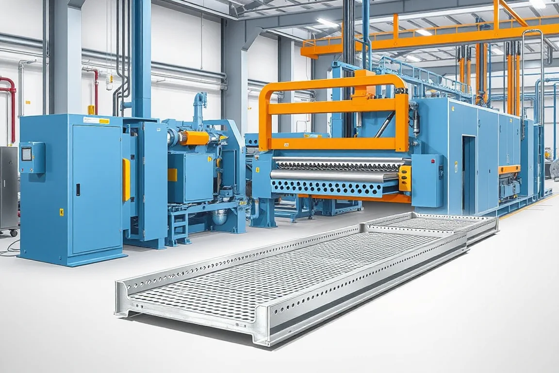
A perforated cable tray production line coordinates repeated feature-making with the forming of a finished tray. The main technical question is how the hole or slot pattern, side walls and edge details remain correctly related across the required widths, materials and lengths.
Compared with a plain-tray route, the punching process can become a major part of both the cycle and the quality-control plan. Selecting the former without reviewing the actual perforation schedule risks a line that makes an attractive sample but cannot deliver the intended catalogue efficiently.
What makes a perforated tray a defined product?
The drawing combines a channel section with a controlled pattern in its base or sides. Connection holes and end details may differ from the repeating perforations. The product also needs the specified edge condition, finish and compatibility with couplers or covers.
Perforation should not be treated as a generic visual texture. Its shape, spacing and position belong to the product design. A pattern selected only because it is easy to punch may not correspond to the tray that customers expect to receive.
Which pattern information should be supplied?
Provide a dimensioned flat or developed pattern together with the finished tray drawing. Show how the two relate. This allows the equipment review to identify features near bends, returns and cut ends rather than discovering those interactions during commissioning.
- Hole or slot geometry and orientation.
- Longitudinal and transverse spacing.
- Edge distances and clear zones at bends.
- End-connection features and their references.
- Pattern changes for each width and side height.
- Specified burr and surface-condition criteria.
Include representative variants rather than one easy sample. A wide tray with several rows of slots can create a different punching workload from a narrow tray with a simple center pattern.
How should punching and forming be coordinated?
The proposed line must preserve the relationship between features and the finished section. Where punching occurs on flat strip, the pattern needs to account for the subsequent bends. Where features are produced later, tool access and support of the formed profile need explanation.
Ask which datums control the repeat pattern, end holes and cut length. These may involve different control functions. A repeated pattern can look consistent while its relationship to the ends is wrong, so the trial should measure both.
The machine proposal should also explain how an interrupted order resumes. Features and cutting must remain coordinated after a stop or coil transition, with startup pieces identified rather than silently added to the accepted count.
What is the complete production sequence?
- Verify material and select the released width-pattern configuration.
- Present and guide the strip through the proposed feed arrangement.
- Create repeating perforations and required connection features.
- Manage punched scrap and preserve strip condition.
- Form the tray walls and functional edge details.
- Cut the ordered length and inspect the finished feature relationships.
- Collect, identify and pack accepted trays.
The exact arrangement can vary, but every required operation should appear in the supply and trial scope. A forming-only demonstration does not establish the performance of a perforated production line.
How does the pattern affect practical output?
Feature density, available tooling and the chosen punching method can influence the cycle. The relevant comparison uses the actual pattern and material, not a nominal feed speed with tools inactive. Short trays can add frequent end-feature and cutoff events.
Build a trial order containing the most common product and a demanding regular variant. Record accepted parts, feature operations, stops, changes and scrap. This reveals whether punching, forming, cutting or collection limits the useful result.
For planning arithmetic only, a pattern requiring 20 repeated positions per tray creates 2,000 positions across 100 trays. The number of machine cycles depends on the tool arrangement and operations performed together. Do not convert pattern counts directly into a production rating without that information.
What changes when tray width changes?
A wider tray may need a different number or placement of perforation rows as well as a new forming width. The configuration should identify strip width, punch tools or programs, side-forming positions and cutoff settings together.
Request a width-pattern matrix that shows supported combinations. Some changes may be programmable, while others require tools or manual repositioning. A powered former adjustment does not establish equivalent flexibility in the punching section.
Demonstrate a meaningful transition and the first accepted tray after it. Check clear zones at bends, end holes, wall dimensions and any lid or coupler fit. Then recover the original setup to verify repeatability.
How should material and perforated-strip behavior be reviewed?
Specify grade or alloy, thickness, finish and width for each pattern family. Removing material changes the strip presented to the forming tools, so trials should use the actual perforated layout. A successful solid-strip run is not enough to establish the finished perforated result.
Inspect local distortion around features, edge condition and the relationship between the base and walls. Record the incoming coil and setup alongside measurements. If a later batch shows waviness or changed dimensions, those records help separate material, pattern and forming causes.
Different metals and finishes require their own review. Stainless steel, coated steel and aluminum should not be treated as equivalent simply because the same pattern can be drawn on each.
How should burrs and punched waste be managed?
Define the required edge condition for cable-contact and assembly surfaces. Inspect the finished tray, including holes near bends and ends. A broad outside-face inspection can miss the areas most relevant to the product's use.
The equipment needs a clear route for punched waste and access for tool service. Waste should not accumulate where it can mark the strip, obstruct the process or be carried into finished bundles. Review the actual collection arrangement during the production trial.
Tool inspection and correction must follow the manufacturer's isolation and maintenance procedures. Do not treat reaching into an operating punching or forming area as a normal way to solve a scrap or burr problem.
Why test couplers and covers after perforation?
The final tray combines section geometry and features. Perforation-related distortion or incorrectly placed connection holes can affect the way neighboring sections join. Use completed production-intent trays and the specified accessories in the assembly check.
Inspect alignment, engagement and the condition of the ends without unplanned reshaping or hole modification. Where a lid is included, check its fit along a normal section rather than only on a short unperforated reference.
Keep manufacturing compatibility separate from the system's required load or electrical performance verification. Those remain tied to the applicable product design and evidence.
How should finished trays be collected?
Define stacking and nesting for the actual width and wall-height range. Perforated sections should be handled without damaging their edges or changing their geometry. Check the product after normal bundle movement, not only at the cutting exit.
Labels should identify size, pattern, material, length and order. Two trays with the same section but different perforation or end-hole schedules are different products. Keep setup scrap, rejected pieces and accepted bundles physically distinct.
What belongs in the quotation and acceptance scope?
Include feed equipment, punching capacity for the stated patterns, all required tools, forming configurations, cutoff, waste handling, takeoff and inspection aids. Identify which future patterns require new tooling and which fall within existing controls.
- Run actual repeating and end-feature patterns.
- Measure finished tray dimensions and feature datums.
- Inspect burrs, local distortion and surface condition.
- Verify coupler and cover interfaces where required.
- Demonstrate width-pattern changes and recovery after interruption.
- Inspect normal packed bundles.
- Report accepted output with all required operations active.
A good acceptance record connects the drawing, material, tools, settings and result. It gives the factory a repeatable configuration rather than a sample that cannot be reproduced after the commissioning team leaves.
Frequently asked questions
Is a perforated-tray line just a tray former with a punch?
It needs coordinated feeding, patterns, forming, cutting and waste handling. The punch is important, but integration determines whether the finished features remain correctly positioned across widths and lengths.
Can every hole pattern be programmed?
Only patterns supported by the installed tools and motion arrangement. Different shapes or locations may need additional dies or setup. Provide the full catalogue and identify each supported configuration.
Why test perforated rather than solid strip?
The openings change the material presented to the forming process. Local distortion and finished dimensions can differ. A solid-strip demonstration does not represent the complete perforated product.
What usually limits the production rate?
It depends on the actual pattern, length and equipment. Punching, cutting or collection can dominate different orders. Measure accepted trays with all required operations active instead of relying on a forming-speed headline.
Should end holes share the repeating pattern reference?
Use the product drawing's datums. Repeating base slots and connection holes may need different relationships to the cut ends. The control and inspection plan should make those references explicit.
What should be sent for an enquiry?
Provide finished tray drawings, developed patterns, material combinations, widths, heights, lengths and accessory references. Add expected order mix and edge-quality requirements. This defines a realistic perforated-tray production and acceptance plan.

Continue your research
- Cable Tray Roll Forming Machines
- Cable Tray Roll Forming Machine
- Cable Ladder Roll Forming Machine
- Solid Bottom Cable Tray Roll Forming Machine
- U Channel Cable Tray Roll Forming Machine
- Cable Support Channel Roll Forming Machine
- How Cable tray roll forming machine Works
- How To Choose a Cable tray roll forming machine
- Cable tray roll forming machine Price: What Affects the Cost?
Configuration & specification inputs
Match the configuration to your section drawing, material and production requirements.
| Parameter | Requirement / confirmation needed |
|---|---|
| Profile geometry | Perforated tray section linked to developed base/side and end-feature patterns |
| Material | Specified grade, thickness and finish tested with actual perforation layouts |
| Thickness & grade | Pattern-specific material combinations across the approved width range |
| Process route | Controlled feed, repeated and end punching, waste handling, tray forming, cutoff and inspection |
| Cutting | Maintain the relationship between repeat patterns, connection holes and cut ends |
| Output | Accepted patterned trays including punching duty, changes, waste handling and collection |
| Electrical supply | Confirm utilities for feed, punching, forming, cutoff and scrap/finished-product handling |
| Acceptance | Measure completed pattern datums, inspect burrs and distortion, fit accessories and demonstrate width recovery |