
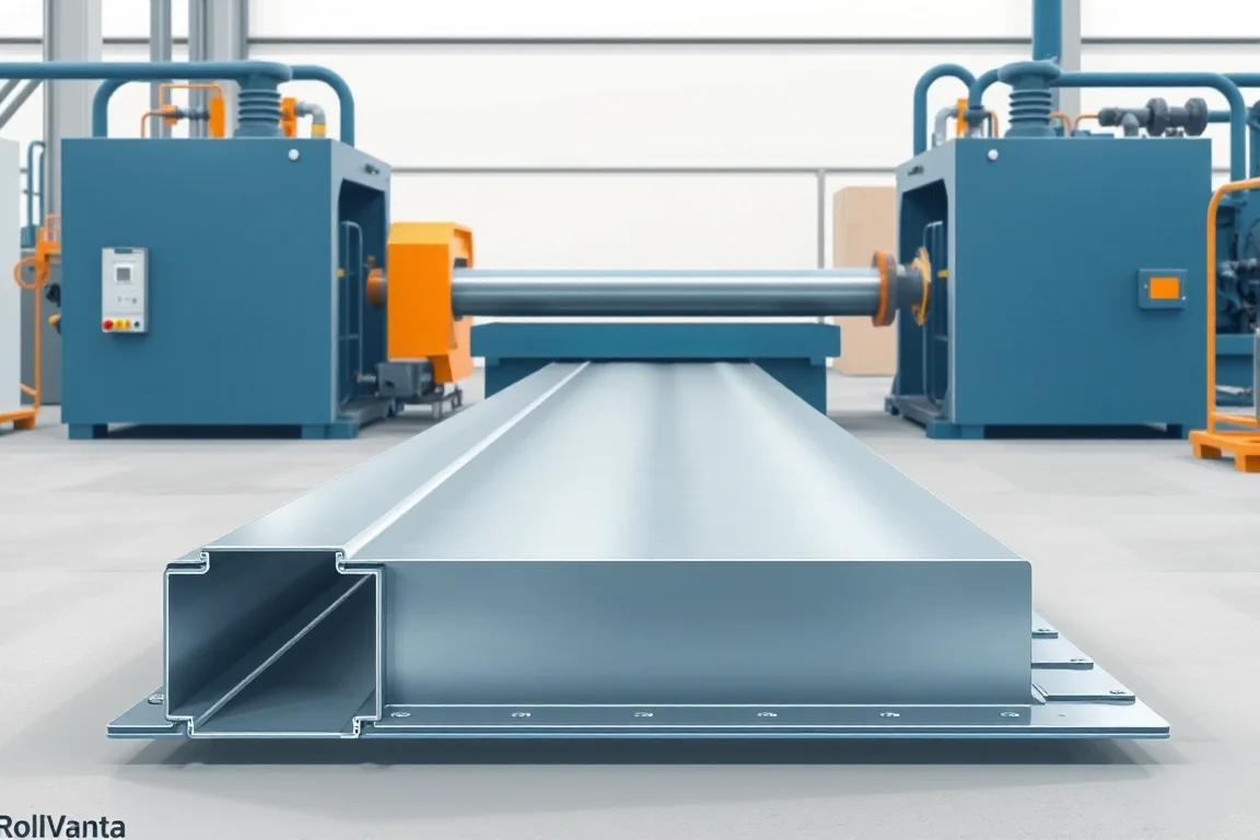
A cable trunking roll forming machine produces the metal bodies or covers used by a specified enclosed cable-routing system. The important manufacturing relationship is between the body, its lid and the connecting accessories. A channel that looks correct on its own can still be unusable if the cover will not engage or neighboring sections cannot join cleanly.
The project should define the complete trunking family before machinery is selected. Body width, wall height, edge returns, cover geometry, connection holes and material finish all affect the route. They also determine whether a shared production system is practical or separate body and lid equipment is preferable.
How is trunking different from an open cable tray?
Trunking is specified as an enclosure arrangement with a corresponding cover and accessories, whereas an open tray has another construction and installation role. The distinction matters to edge geometry, fit and the scope of the manufacturing project.
Do not infer a particular protection rating merely from the presence of a lid. The complete product design, joints, fittings and required verification determine its intended performance. The forming line's job is to reproduce the specified components accurately.
What should the body drawing establish?
Show the usable width, side height, bottom bends and top-edge construction. Identify the surfaces or returns that retain the lid and the datums used by couplers or end fittings. State internal and external dimensions clearly rather than relying on a nominal catalogue size.
- Base and wall dimensions with radii.
- Lid-retaining lips, hems or fastening flanges.
- Connection holes, slots and required knockouts.
- Material, thickness and finish.
- Length range and end condition.
- Divider and accessory interfaces where included.
Include the body and lid in an assembled section drawing. This shows clearances and engagement more effectively than two unrelated component sketches.
How should the cover be specified?
The cover needs its own profile drawing, material and manufacturing tolerances. It may clip onto formed edges or attach through another defined method. Its width and returns should be referenced to the intended body rather than selected independently.
Identify removal and refitting expectations as part of the product design. A lid that can be forced onto one short sample may not engage consistently along a normal section. Use representative lengths and the intended assembly sequence during trials.
Specify visible-face requirements where trunking is exposed. Cover and body finish should be coordinated, including color identification and surface protection during nesting or transport.
What does the manufacturing route include?
Body production combines coil presentation, required feature-making, progressive side and edge forming, cutting and collection. Cover production follows its own profile route. The equipment proposal should explain whether these use separate lines, shared changeable tools or another arrangement.
- Confirm the released body or cover configuration and material.
- Guide the strip and make the specified features.
- Develop the main bends and functional edge returns.
- Cut to the ordered length with suitable support.
- Inspect component dimensions and surface condition.
- Pair representative bodies and covers, then identify and pack accepted output.
Any secondary operation should have a clear place in the route. Knockouts, end processing or fitting fabrication should not remain undefined simply because the main channel can be roll formed.
What does an adjustable-width system cover?
Width adjustment may reposition side-forming paths while retaining one edge and wall-height arrangement. It does not automatically alter every body dimension or create the corresponding cover. Ask for a configuration matrix showing body and lid variants together.
For each width change, identify input strip widths, guides, punching programs, cutoff components and cover settings. Demonstrate the complete transition and inspect a matched pair. A body-only width demonstration leaves the enclosure interface unproven.
Separate width, height and edge-design changes in the quotation. They can require different levels of adjustment or tooling, and treating them as one generic size change obscures both cost and production effort.
How should holes and knockouts be reviewed?
Provide the exact feature pattern and its purpose. Connection holes, mounting slots and knockouts have different production and inspection requirements. Define their position relative to bends, edges and cut ends.
Inspect features on the finished body. Forming can change their spatial relationship, and local distortion can affect cover or coupler fit. For knockouts, use the product's specified retention and removal criteria rather than judging only their visible outline.
Plan scrap handling and tool access. Feature-making should be demonstrated with the actual commercial pattern, since a plain-channel run does not establish the line's output or quality when all required operations are active.
How should material and finishing be coordinated?
Specify grade or alloy, base-metal thickness, coating and finish for bodies and covers separately. The two components need compatible production and appearance requirements, but they should not be assumed to use identical strip dimensions or tooling.
Define whether finishing occurs before or after forming and how it affects final fit. A coating applied later can be relevant to clearances and contact surfaces, so acceptance should address the product in its intended final condition.
Retain material and color identification through storage. Similar bodies or covers can be mixed easily when several orders run in parallel, creating an assembly problem unrelated to machine accuracy.
How can lid engagement be tested meaningfully?
Use production-intent components of representative lengths. Follow the intended fastening or clipping method and inspect engagement along the section, including near cut ends. Check whether the cover sits as designed without unplanned spreading, squeezing or trimming.
Record tightness, looseness, uneven gaps and surface marks separately. A cover that appears seated may have been distorted during fitting, which is why the condition after removal or refitting can also be relevant to the selected product design.
If fit differs across batches, compare body and cover dimensions, materials, finishing and handling. Adjusting one component to match a faulty example of the other can create two incorrect product streams.
Which accessories need separate production planning?
Bends, tees, reducers, end caps, couplers and dividers may use cutting, bending, stamping or joining processes outside the straight-profile line. Define the accessory catalogue and decide which products are made in-house and which are purchased.
Review their interfaces with finished straight sections. A useful trial package includes representative couplers or end fittings, not only body-and-lid engagement. The complete routing system requires those relationships to remain consistent.
What handling and identification are useful?
Define whether bodies and covers are packed together or separately, how they nest and how the finish is protected. Packing should not spread the retaining edges or damage cover returns. Inspect normal packs after handling.
Labels should distinguish size, profile revision, material, finish and order. A cover with a slightly different return can look interchangeable in storage, so clear product references are more reliable than visual sorting.
Provide separate routes for startup pieces, rejects and parts awaiting finishing. The production count should reflect accepted components rather than every piece cut from the coil.
How should complete-system output be compared?
Measure accepted matched body-and-cover quantities for the intended order mix. If one route makes bodies faster than covers, the unmatched stock is not the same as dispatch-ready trunking. Include accessories where they are part of the delivery commitment.
Compare quotations for equivalent body and cover matrices, feature tools, cutoff, handling and inspection. Identify the labor and time needed for shared-machine changes. A low-cost body former and a coordinated enclosure-production package address different scopes.
For planning only, an order of 300 body sections and 300 matching covers requires both accepted quantities. Producing 600 bodies does not complete it. This simple balance is useful when selecting shared versus dedicated component routes.
What should acceptance prove?
- Body and cover cross-sections in the actual materials.
- Length, ends and all required feature positions.
- Engagement along representative complete sections.
- Coupler and accessory fit.
- Required size changes and recovered matched production.
- Finish and edge condition after packing.
- Accepted component balance for a representative order.
Retain matched reference samples and the associated setup records. These provide a practical benchmark for later investigations of fit or appearance.
Frequently asked questions
Does a trunking-body machine also make lids?
Only if the cover tooling and production arrangement are included. The lid is a separate profile with its own functional returns. Specify both components and demonstrate a matched pair.
Does a lid establish a protection rating?
No. The complete enclosure design, joints, fittings and relevant verification determine its performance. Manufacturing fit is one requirement, not a substitute for the applicable product evidence.
Can width change without new tools?
It may within the agreed configuration, but height and retaining-edge geometry can remain fixed. Review body and cover changes together, including strip widths, feature programs and cutoff support.
Are knockouts the same as ordinary holes?
No. They have their own retained and removable feature requirements. Provide the drawing and acceptance criteria. A generic punching capability does not establish a satisfactory knockout process.
Why test finished coated components?
The final surface condition can affect fit and appearance. A successful uncoated sample does not automatically represent the delivered enclosure. Coordinate the finishing route with component and assembly inspection.
What should an enquiry contain?
Send matched body and cover drawings, features, materials, finishes, lengths and accessory scope. Add the expected size mix and packing method. This defines a complete trunking-production requirement.

Continue your research
- Cable Tray Roll Forming Machines
- Cable Tray Roll Forming Machine
- Cable Ladder Roll Forming Machine
- Solid Bottom Cable Tray Roll Forming Machine
- U Channel Cable Tray Roll Forming Machine
- Cable Support Channel Roll Forming Machine
- How Cable tray roll forming machine Works
- How To Choose a Cable tray roll forming machine
- Cable tray roll forming machine Price: What Affects the Cost?
Configuration & specification inputs
Match the configuration to your section drawing, material and production requirements.
| Parameter | Requirement / confirmation needed |
|---|---|
| Profile geometry | Trunking body and matched lid with controlled retaining and connection edges |
| Material | Separate body/cover materials and finishes coordinated in the final assembly |
| Thickness & grade | Approve actual component combinations rather than one generic channel range |
| Process route | Component-specific features and forming, end preparation, matched fit inspection and packing |
| Cutting | Protect retaining returns and end-related features on bodies and covers |
| Output | Accepted matched body-and-cover quantities with required accessories separately scoped |
| Electrical supply | Confirm utilities for body and cover routes, features, cutoff and packaging |
| Acceptance | Measure both components, test lid engagement and couplers, and inspect finished packed condition |