
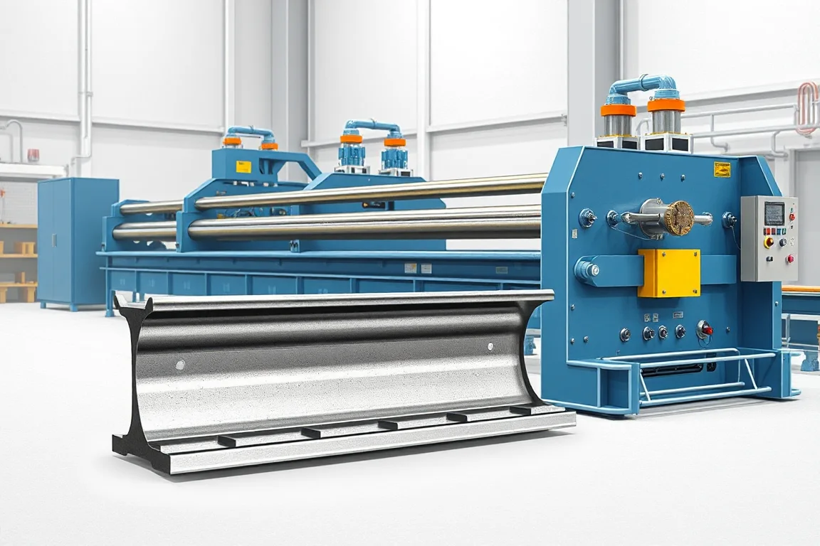
A guardrail post roll forming machine manufactures the specified cold-formed posts used within a roadside barrier system. The post is a different component from the corrugated rail: its cross-section, attachment holes, length and connection to spacers or other parts define a separate production task.
C, U and sigma-shaped posts are examples of profiles that can require dedicated roll-forming configurations. The equipment should follow the approved post drawing, not a general assumption that any strong-looking channel can replace another post in the same barrier. Component geometry and system use must remain connected.
Which post family is required?
Begin with the complete cross-section and its intended orientation in the barrier. An open U channel, a lipped C section and a sigma profile have different bend sequences and functional surfaces. Their hole patterns and mating components can also differ.
If the project includes posts made by another process, identify those separately. A roll-forming line for sheet-derived sections is not automatically a route for every tubular, hot-rolled or fabricated post. Compare manufacturing methods against the actual product rather than forcing all barrier components into one machine category.
What should the drawing package show?
Include the post section, finished length, both ends and every required feature. Identify which surfaces locate the rail or spacer and which datums control hole positions. The installation orientation should be unambiguous so asymmetric features are not mirrored accidentally.
- Web, flanges, lips or sigma offsets with bend radii.
- Material grade, thickness and surface requirements.
- Attachment holes and slots measured from finished references.
- Top and bottom end condition, including special operations if required.
- Mating spacer, rail or connection drawings.
- Product identification and required final inspection.
List length variants and their feature patterns together. A shorter post is not necessarily produced by changing only the cutoff length if the attachment or end references also change.
How does a post line operate?
The route presents the coil, controls entry, creates the specified features, develops the section progressively and cuts the ordered length. Collection and any subsequent finishing complete the manufacturing flow. The exact sequence depends on the proposed tooling and controls.
- Verify the released post configuration and coil identity.
- Load and guide the strip within the line's agreed envelope.
- Produce the required attachment features.
- Form the web, flanges, lips or offsets through successive passes.
- Cut and support the post without unacceptable local deformation.
- Inspect and group accepted parts for finishing or dispatch.
Ask how the feature datums are maintained through forming and cutoff. The final post, rather than an intermediate flat strip, is the relevant object for checking the connection geometry.
What changes between C, U and sigma posts?
The section shapes create different forming and tool-access requirements. A C profile includes returns that an open U may not have, while a sigma section introduces additional offsets. These differences affect the pass sequence, supporting tools and the dimensions that need inspection.
A multi-profile proposal should state which tools are shared and which are replaced. Include entry guides, punch tools, cutoff parts and collection supports in the changeover plan. The ability to alter one web dimension does not establish the ability to transform one section family into another.
Demonstrate the required transitions and return to an accepted original setup. Record first-good-product time, setup scrap and inspection effort. This is the useful measure of flexibility for a factory processing varied post orders.
How should material combinations be reviewed?
Specify grade, thickness, strip width and coating route together for each post family. Material response affects springback, bend condition and the final attachment surfaces. A thickness range alone cannot describe the complete forming duty.
Use representative production material during trials and retain its identity with measured samples. If a later batch shows a different flange opening or offset, compare material and setup before changing the tools. The investigation should be based on recorded conditions rather than a visual guess.
Keep material records linked through any downstream coating or fabrication. Different post specifications can appear similar after finishing, making clear identification important for both the factory and the receiving customer.
Why are hole references especially important?
A post's holes locate the rail, spacer or other connection components. Their relationship to the section and to the designated end must match the drawing. A hole pattern can have the correct internal spacing yet still be wrong because the entire pattern is referenced from the wrong end.
Check orientation, size and position on the completed post. Include burr and distortion observations. If features occur on different faces, the inspection method should make their relationship clear rather than treating each face as an unrelated flat pattern.
Assemble the intended spacer or attachment components during acceptance. This helps reveal access and fit issues, but it should complement dimensional checks rather than replace them with a forced assembly.
What end operations need separate scope?
Define the required condition of both post ends. If the product includes a special cut, local forming, cap, base plate or other fabricated feature, identify the process that creates it. A straight cutoff does not automatically provide every installation-specific end detail.
Posts intended for different installation arrangements may require different manufacturing routes even when their main section is similar. The machine proposal should make those boundaries explicit, including whether secondary drilling, welding or finishing is included or performed elsewhere.
Inspect the final component after the required operations. An intermediate roll-formed length is not the same acceptance object as a post with its complete end and attachment details.
How should straightness and section condition be measured?
Use agreed support and measurement references on production-length posts. Check the section near the ends and at intermediate locations. Local cutoff distortion, persistent twist and a shifted sigma offset are different deviations and should be recorded separately.
Where an issue appears after another operation, compare before-and-after measurements. Handling, finishing or secondary fabrication can alter the part after forming. Corrective action should address the actual source and follow the responsible engineering and equipment procedures.
Retain accepted samples and setup sheets for every post family. A shared line benefits from clear configuration references because visually similar tools or settings can produce meaningfully different connection geometry.
How should posts be collected and identified?
Define nesting, bundle size and the movement method for each section. Open profiles and offset shapes may pack differently. The handling route should prevent damage to attachment features and allow reliable counting without mixing configurations.
Labels should identify section, length, pattern, material and production reference. Separate accepted parts from setup scrap and from components awaiting another operation. The factory should be able to distinguish a finished post from a formed blank at a glance.
What should output and cost comparisons include?
Measure accepted complete posts for a representative order with the required holes and end operations included. Forming speed alone omits punching, cutting, secondary work and collection. If the project relies on a separate finishing process, account for its role in the overall delivery schedule.
Compare quotations for equivalent product families, tools, controls, coil handling and inspection. Identify separate equipment for spacers, rails or other barrier parts rather than assuming they are included with the post line.
For arithmetic only, an order of 600 posts at 1.8 metres each contains 1,080 metres of finished post length. It does not define installed barrier coverage, because post spacing and the system layout are separate design inputs. Avoid using one quantity as a substitute for the other.
What should acceptance demonstrate?
- The complete section in each agreed material combination.
- Finished length, end condition and feature orientation.
- Hole positions from the correct functional datums.
- Fit with intended spacers or attachment components.
- Straightness and twist under the agreed method.
- Required changes between post configurations.
- Final identification, bundle condition and accepted output.
The trial establishes a manufacturing reference for the specified post. It does not independently qualify a complete roadside barrier or justify substituting the post into another system.
Frequently asked questions
Can a guardrail-beam line make posts?
Not automatically. Posts require their own cross-sections, feature tools and handling review. A supplier may offer coordinated equipment for both components, but each production route should have an explicit scope.
Are C and sigma posts interchangeable?
Use the post specified by the approved barrier arrangement. Different shapes and connections should not be substituted based on appearance or an assumed strength comparison. Manufacture the controlled component drawing.
Can one post line cover several lengths?
A configured line may do so, but the corresponding feature positions and end details must remain correct. Demonstrate the required length-pattern combinations rather than changing the cutoff setting alone.
Does the line include galvanizing?
Only if that separate process is explicitly part of the project. Define the coating route, handling and final inspection responsibilities. A roll former by itself is not a complete finishing plant.
Why check which end the holes reference?
Post orientation matters. A pattern can have correct spacing but sit incorrectly on the finished component if its datum is reversed. Clear drawings, part identification and final inspection prevent that confusion.
What should an enquiry include?
Provide section, feature and end drawings, material combinations, lengths, coating route and mating components. Add quantities and bundle requirements. This makes the proposal specific to the posts the factory intends to deliver.

Continue your research
- Guardrail & Crash Barrier Roll Forming Machines
- W Beam Guardrail Roll Forming Machine
- Thrie Beam Guardrail Roll Forming Machine
- Guardrail C Post Roll Forming Machine
- Guardrail Sigma Post Roll Forming Machine
- Guardrail U Post Roll Forming Machine
- How Guardrail roll forming machine Works
- How To Choose a Guardrail roll forming machine
- Guardrail roll forming machine Price: What Affects the Cost?
Configuration & specification inputs
Match the configuration to your section drawing, material and production requirements.
| Parameter | Requirement / confirmation needed |
|---|---|
| Profile geometry | Specified post web, flanges, lips or sigma offsets and attachment interfaces |
| Material | Approved post grade and finish linked to each production batch |
| Thickness & grade | Section-specific grade, thickness and width envelope |
| Process route | Identified coil, post feature-making, progressive forming, cutoff and required secondary operations |
| Cutting | Verify both ends and any separate cap, base or installation-specific treatment |
| Output | Accepted complete posts with correct features and final identification |
| Electrical supply | Confirm utilities for the selected post tools, feature operations and handling |
| Acceptance | Measure section, end-referenced holes and orientation; fit intended spacers and inspect packed posts |