
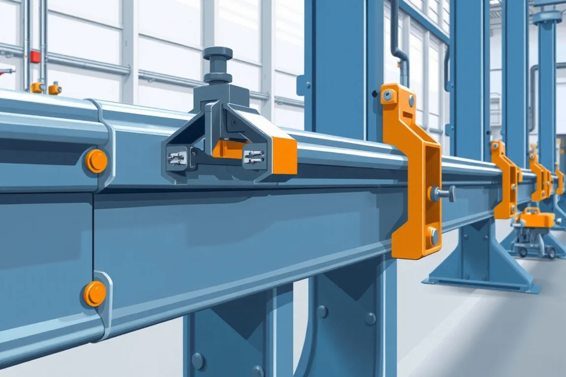
Maintenance of a guardrail roll forming machine is not a single task but a sequence of checks that protect profile geometry, tooling life and operator safety. The goal is to keep wave shape, splice-hole position, lap fit and beam length within drawing tolerance while preserving the machine’s guards, emergency systems and reference datums. This checklist explains what to inspect, why each point matters, and how to verify that maintenance has not shifted the product. It applies to machines producing W-beam, thrie beam or other barrier profiles from specified barrier-system steel.
Start With the Approved Drawing and Material Certificate
Every maintenance decision begins with the approved profile drawing and the material certificate for the coil being run. The drawing defines beam waves, bolt-slot pattern, lap orientation and post connection geometry. The material certificate states grade and coating sequence. If maintenance changes any roll gap, punch position or cutoff reference, the first production must be compared against these documents. Without them, a machine can appear to run correctly while producing beams that will not fit at installation.
Punch Tooling: Wear, Alignment and Splice Datums
Punch tooling is the most dimensionally sensitive area. Inspect punch tips for wear, chipping or galling. Check die clearance and stripper condition. The critical point is that punch tooling must reference the splice datums, not merely the beam edge. If punches are replaced or shimmed, verify that the bolt-slot pattern still aligns with the drawing’s longitudinal and transverse datums. A small shift in punch position can cause splice holes to miss the intended lap fit even when the wave geometry looks acceptable.
Cutoff Edges and End Quality
Cutoff quality affects both appearance and function. Inspect the cutoff blade or shear for dull edges, cracks or misalignment. Check that the cutoff is profile-supported so the beam does not deform during cutting. Look for burrs, distortion or angled ends. Burrs can interfere with lap fit and coating. If end quality changes after maintenance, record the change and verify cut length and end squareness against the drawing before releasing production.
Scrap Removal and Material Flow
Scrap removal is often overlooked until it causes a jam. Check that slugs, trim and offcuts exit the machine without accumulating near moving parts or sensors. Blocked scrap can damage rolls, interrupt production or create a safety hazard. Inspect chutes, conveyors and collection bins as part of the maintenance routine. Also confirm that coil feed, leveling and forming sections are clean and free of debris that could mark the beam surface or coating.
Rolls, Shafts and Forming Stations
Inspect roll surfaces for wear, buildup or damage. Check shaft bearings for play, noise or excessive temperature. Verify that roll gaps and alignment match the setup sheet for the current profile. Because guardrail sections are long, any misalignment can produce twist, camber or wave distortion that accumulates over the beam length. Maintenance should include checking that station references have not shifted and that locking devices are secure.
Guards, Emergency Systems and Safe Restart
Guards and emergency systems are not optional. Confirm that all guards are in place, interlock devices function and emergency stops are accessible. Never bypass guarding to keep production running. After any maintenance, follow the equipment maker’s isolation and restart procedure. Assign work to trained personnel. Verify safe restart before normal production. Maintenance that improves output but compromises safety is not acceptable.
First-Piece Verification After Maintenance
After maintenance, verify the first production piece before running the shift. Inspect wave geometry, splice-hole position, lap fit and beam length. Use the same measurement methods as normal production acceptance. Keep component dimensional acceptance separate from system crash-testing and installation approval. A dimensionally correct beam is not the same as a crash-tested barrier system. Document the first-piece results and compare them with pre-maintenance records to detect drift.
Checklist for Routine Maintenance
- Review the approved drawing and material certificate for the current profile.
- Inspect punch tips, dies, strippers and splice-datum alignment.
- Check cutoff edges, profile support and end quality.
- Clear scrap and verify removal paths are unobstructed.
- Inspect roll surfaces, bearings, shafts and station alignment.
- Confirm guards, interlocks and emergency stops are functional.
- Follow the equipment maker’s isolation and restart procedure.
- Produce and inspect a first piece for wave geometry, splice holes, lap fit and length.
- Record inspection, replacement and setup changes.
- Assign work to trained personnel and document any change that could affect product dimensions.
Component Production Versus System Approval
Maintenance keeps the machine producing components within dimensional tolerance. It does not certify the barrier system. Posts, beam sections and spacer blocks may require different processes; do not assume one line makes the entire barrier. Crash-testing and installation approval are separate activities. Understanding this boundary prevents overclaiming and helps maintain the right records for each stage.
How to Diagnose Common Symptoms Without Hazardous Intervention
If wave geometry drifts, inspect roll alignment, material feed and leveling settings against the setup sheet. If splice holes misalign, check punch datum references and tooling wear. If cutoff ends show burrs, examine blade condition and profile support. If scrap accumulates, inspect removal paths. In every case, isolate the machine using the approved procedure before inspection or adjustment. Do not adjust moving machinery. Use diagnostic evidence such as first-piece measurements, maintenance logs and setup records to identify the cause, then follow the equipment maker’s instructions for correction.
FAQ
How often should I inspect punch tooling?
Inspection frequency depends on production volume, material grade and coating. The equipment maker’s manual provides the recommended interval. In practice, check punch tips and die clearance whenever first-piece verification shows splice-hole drift or when a new coil lot is introduced. Record each inspection so patterns become visible.
What should I do if the cutoff edge becomes dull?
Dull cutoff edges can cause burrs, distortion or angled ends. Stop production using the approved procedure, inspect the blade for wear or damage, and replace or sharpen according to the equipment maker’s instructions. Verify cut length and end quality on the first piece after correction.
Can I adjust roll gaps to improve wave geometry?
Roll gaps affect wave shape and should be set according to the setup sheet for the profile. If wave geometry drifts, first check for wear, misalignment or material variation. Adjustments must be made by trained personnel following the equipment maker’s procedure, with first-piece verification afterward.
Why is scrap removal part of maintenance?
Scrap that accumulates can jam feeds, damage rolls or create safety hazards. Clearing scrap and inspecting removal paths prevents unplanned downtime and protects the machine. It also reduces the risk of debris marking the beam surface or coating.
How do I know maintenance has not affected product acceptance?
Compare first-piece measurements after maintenance with the approved drawing and pre-maintenance records. Check wave geometry, splice-hole position, lap fit and beam length. Keep component dimensional acceptance separate from crash-testing and installation approval. Document the results.
What records should I keep for maintenance?
Keep a log of inspections, replacements, setup changes and first-piece results. Include the date, personnel, machine settings and any observed drift. These records help trace dimensional changes and support consistent production.
Practical Alternatives When Maintenance Needs Escalate
If recurring issues point to worn rolls or outdated tooling, options include reconditioning existing tooling, replacing specific stations or upgrading the line. Each has tradeoffs in cost, downtime and compatibility with existing drawings. A maintenance checklist helps identify when a repair is no longer sufficient and a larger decision is needed.
Continue your research
- Guardrail & Crash Barrier Roll Forming Machines
- W Beam Guardrail Roll Forming Machine
- Thrie Beam Guardrail Roll Forming Machine
- Guardrail C Post Roll Forming Machine
- Guardrail Sigma Post Roll Forming Machine
- Guardrail U Post Roll Forming Machine
- How Guardrail roll forming machine Works
- How To Choose a Guardrail roll forming machine
- Guardrail roll forming machine Price: What Affects the Cost?