
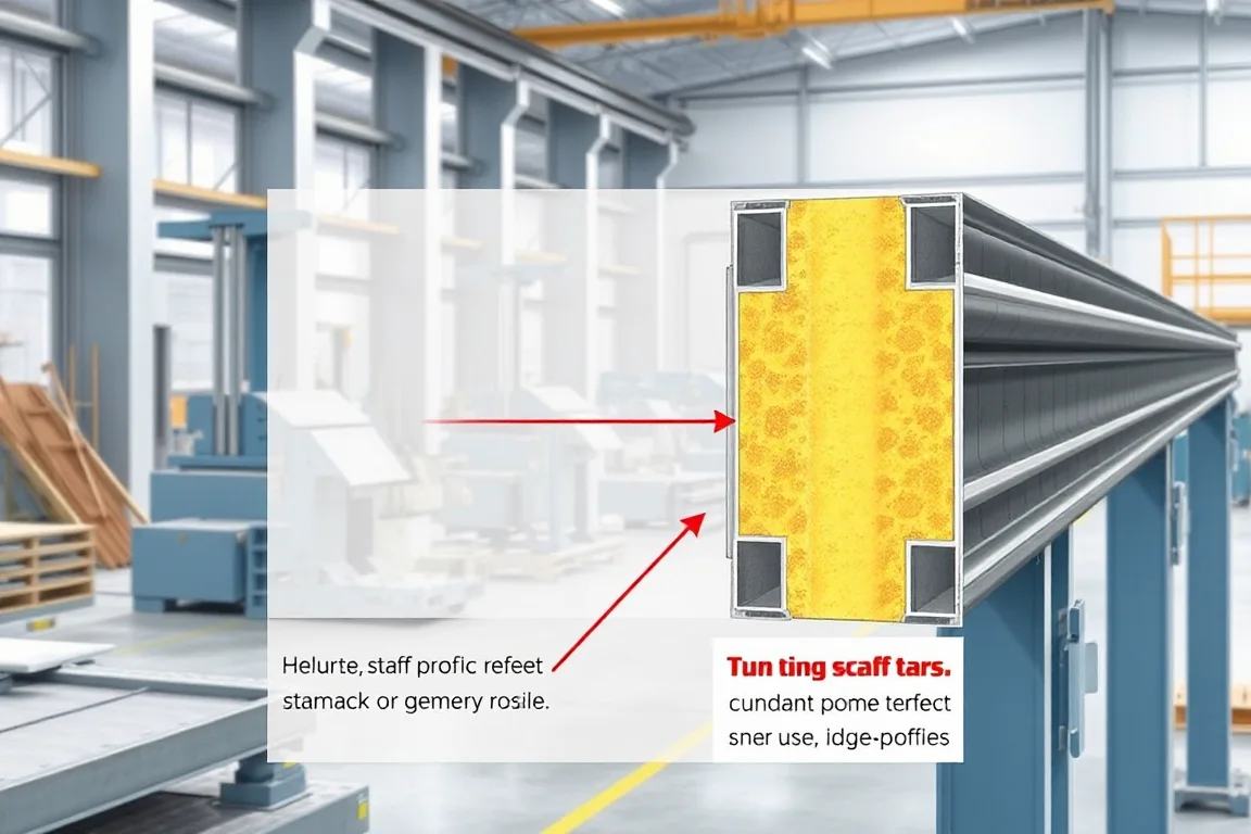
Scaffolding roll forming is not a single act of bending strip into a shape. It is a chain that begins with coil condition and ends with a finished walking surface, rib pattern, hook, and attachment interface. Troubleshooting works best when you treat the chain as a sequence of causes rather than a list of machine settings.
The practical question behind this page is simple: when a scaffold plank or component comes off the line out of tolerance, twisted, cracked, poorly seated, or cosmetically wrong, how do you find the real cause without turning the machine into a series of random adjustments? The answer is evidence. You compare known-good references with current output, isolate one variable at a time, and keep forming, cutting, joining, and handling effects separate.
Why scaffolding plank defects rarely have a single cause
A scaffold plank is a structural product with a walking surface, anti-slip features, side ribs, and end fittings. Each feature is created by a different part of the process. A rib that looks shallow may be caused by coil width variation, a worn forming station, a change in material yield, or distortion introduced later by welding. A hook that will not seat may be a cut-length issue, a forming issue, or an end-plate placement issue. Treating the symptom in isolation can move the problem from one station to another.
The useful discipline is to record the defect where it appears and then ask what happened immediately before that point. Incoming material, output before cutoff, the cut part, and the joined assembly are four different states. Comparing them separates a material or forming cause from a cutting, joining, or handling cause.
First evidence to collect before changing anything
Before any adjustment is considered, gather a consistent record. Include the part identity, coil lot, drawing revision, and measurement conditions. Note the ambient and material temperature if the shop varies. Record which stations are engaged and whether the issue began after a coil change, a setup change, or a tooling change. A defect that starts at a coil change points in a different direction from one that appears gradually over a production run.
Measurements need a method. A caliper reading taken at the same point by the same operator is more useful than several readings taken differently. Where a feature is formed, compare a known-good part produced on the same line under the same conditions. Keep that reference part stored so that tool wear, material changes, and handling damage can be checked against something real rather than memory.
Symptoms, likely causes, and the evidence that separates them
Twist or bow along the length. Twist usually relates to uneven forming across the strip, differences in springback from side to side, or a mismatch between the two edges of the coil. Check the strip for camber or edge condition before forming, then compare the output before cutoff with the finished handled part. If twist exists before cutoff but not after handling, the source is upstream. If twist appears only after joining, the joining process or the fixture may be pulling the section.
Inconsistent rib depth or anti-slip pattern. The pattern may be embossed or formed at a specific station. Uneven depth can come from coil thickness variation, inconsistent lubrication, or a worn or mis-shimmed station. Compare the incoming coil thickness across its width and length, then inspect the output before cutoff. If the pattern is correct before joining and shallow after, heating or clamping in the joining process may be the cause.
Cracking or edge tearing. Cracks often begin at a bend or a punched hole. The evidence is the location and orientation of the crack relative to the material grain or forming direction. Check whether the crack follows a sheared edge, a punch burr, or a forming bend. Material grade, thickness, and edge quality interact. A change in coil lot is a common trigger, and the crack location tells you whether forming strain or a cutting burr is the more likely contributor.
Cut-length variation. Cut-length problems can originate from the cutoff die, the feed system, or slip between the strip and the feed rolls. Compare the commanded length with the measured length over several parts and identify whether variation is random or drifting. Random variation points toward slip or a sensor issue; drift points toward thermal change, roll wear, or a changing reference. Confirm profile-supported cutoff and the end quality the drawing requires.
Poor seating or rocking at the end fitting. This is often a joining or assembly symptom rather than a forming symptom. Inspect end attachments and the formed section separately. Welding distortion, hole position, and end-plate alignment can all prevent proper seating. A formed sample that looks correct on the bench may not seat once joined. Load and slip requirements apply to the finished component and system, so they cannot be inferred from a formed sample alone.
Surface finish and coating defects. Marks, scratches, and coating damage can be introduced by handling, guides, or rolls. Trace the part backward: if the mark is present before cutoff but not before forming, the forming section is implicated. If it appears only after the part is moved, handling or stacking is the likely cause. When galvanizing follows welding, the finishing process must account for the full finished component, not just the formed shape.
Why welding distortion should not be corrected at the roll tools
Distortion introduced by welding is a joining effect, not a forming effect. If a joined assembly is twisted or bowed and the formed section was correct before joining, adjusting the roll tools to compensate will change the geometry of every part and may introduce a new defect. The correct response is to examine the welding sequence, fixture, fit-up, and cooling. This is also a reminder to define grade, thickness, coating, and joining requirements together, because a change in one affects the others.
How to compare alternatives when the line cannot hold tolerance
When a line struggles with a scaffold profile, buyers and process owners often consider three broad alternatives: adjust the existing setup, change the tooling or forming strategy, or change the material or cutting approach. Each has a different cost and risk profile.
- Adjusting the existing setup is the lowest-cost option but has limits. It can compensate for minor springback and alignment issues. It cannot fix a tooling design that is wrong for the profile, and repeated adjustment can consume the available adjustment range.
- Changing forming strategy or tooling addresses a mismatch between the profile and the roll design. This is a more substantial change and requires a clear definition of the profile, the material, and the interface requirements. It is justified when the defect is consistent and traceable to the forming sequence rather than to material variation.
- Changing material or cutting method can resolve cracking, burr, or length problems, but it also changes the acceptance conditions. A different grade or coating may meet the walking-surface requirement differently, and a different cutoff method may change end quality. This option should be evaluated against the finished component and the system it belongs to, not only against the formed sample.
In every case, the comparison should be made with like-for-like measurement and the same reference part. A change that improves one feature while degrading another is not an improvement.
Distinguishing scaffold connection systems from sheet profiles
Ringlock and cuplock are names for connection systems. They are not evidence that a ledger or standard is made on a sheet-profile roll former. Confirm whether the component is tube or open-section construction before applying troubleshooting logic from a plank line. A tube-based scaffold component has different forming, cutting, and joining steps, and the defects will present differently. This distinction matters when specifying equipment or interpreting a defect that seems out of character for the line.
A practical troubleshooting checklist
- Record the defect with part identity, coil lot, drawing revision, and measurement conditions.
- Identify whether the fault started at a coil change, a setup change, or a tooling change.
- Compare incoming material, output before cutoff, the cut part, and the finished handled part.
- Keep a known-good reference part and use the same measurement method.
- Separate forming, cutting, joining, and handling effects before changing any controlled variable.
- Change one controlled variable at a time under the equipment manufacturer's procedure.
- Escalate safety-related or qualified-process changes to the responsible engineer.
- Do not reach into running machinery or improvise adjustments around stored energy.
FAQ
Why does a scaffold plank twist even when the strip looks flat?
A strip can look flat and still carry internal stress or camber that only becomes visible after forming. Twist often emerges when forming forces release those stresses unevenly across the width. Compare the strip edge condition and camber, then check whether twist is present before cutoff. If it is, the forming sequence or material condition is the likely area; if it appears only after joining, the joining fixture or sequence deserves attention.
Why does the anti-slip pattern look shallow only after joining?
If the pattern is correct before joining and shallow afterward, the joining process is the likely cause. Heat, clamping pressure, or fit-up can flatten or distort the pattern. Inspecting the formed section separately from the joined assembly is the essential step. Correcting the roll tools in this situation would alter the pattern for every part while leaving the joining cause in place.
What is the first thing to check when cut lengths drift?
First determine whether the variation is random or drifting. Random variation points toward slip, a sensor issue, or inconsistent feed; a steady drift points toward thermal change, roll wear, or a changing reference. Measure several parts and compare them with the commanded length. This evidence narrows the cause before any mechanical change is considered.
Can cracking be solved by adjusting the rolls alone?
Sometimes, but only if the crack originates in forming. If the crack starts at a sheared edge, a punch burr, or a material inclusion, roll adjustment may not address it. Locate the crack relative to the bend, hole, or edge. Material grade, thickness, and edge quality interact, and a coil lot change is a common trigger. The evidence should point to the stage where the crack begins.
Why does a formed sample pass inspection but the finished component still fail to seat?
The formed sample represents only one stage of production. Seating depends on end attachments, hole position, end-plate alignment, and the absence of welding distortion. Inspect the end attachments and the formed section separately. Load and slip requirements apply to the finished component and system, so they cannot be inferred from a formed sample alone.
When should a defect be escalated to an engineer?
Escalate when the defect affects a safety-related feature, when the proposed change alters a qualified process, or when the cause remains unclear after controlled comparison. Troubleshooting should not involve reaching into running machinery or improvising adjustments around stored energy. The responsible engineer can evaluate whether the change is acceptable for the finished component and the system it belongs to.
Continue your research
- Scaffolding Roll Forming Machines
- Scaffold Plank Roll Forming Machine
- Scaffolding Deck Roll Forming Machine
- Ringlock Scaffold Ledger Roll Forming Machine
- Cuplock Scaffold Ledger Roll Forming Machine
- Scaffold Frame Profile Roll Forming Machine
- How Scaffolding roll forming machine Works
- How To Choose a Scaffolding roll forming machine
- Scaffolding roll forming machine Price: What Affects the Cost?