
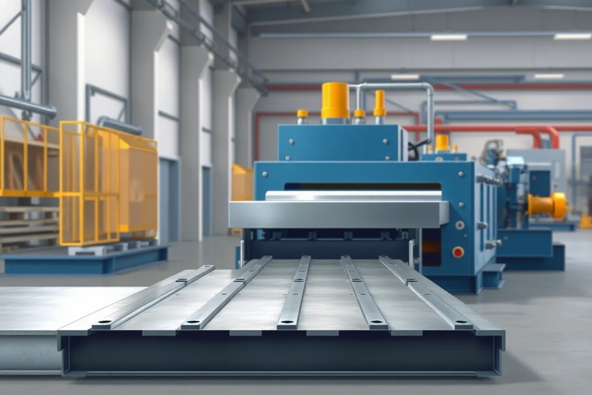
Scaffold-component production can combine roll forming with punching, tube manufacture, joining and other fabrication. Planks, decks, ledgers and frame members do not all follow one process merely because they belong to scaffolding. Select equipment from controlled component drawings and the actual connection system, not from a general scaffold-machine description.
Separate platform members from other scaffold components
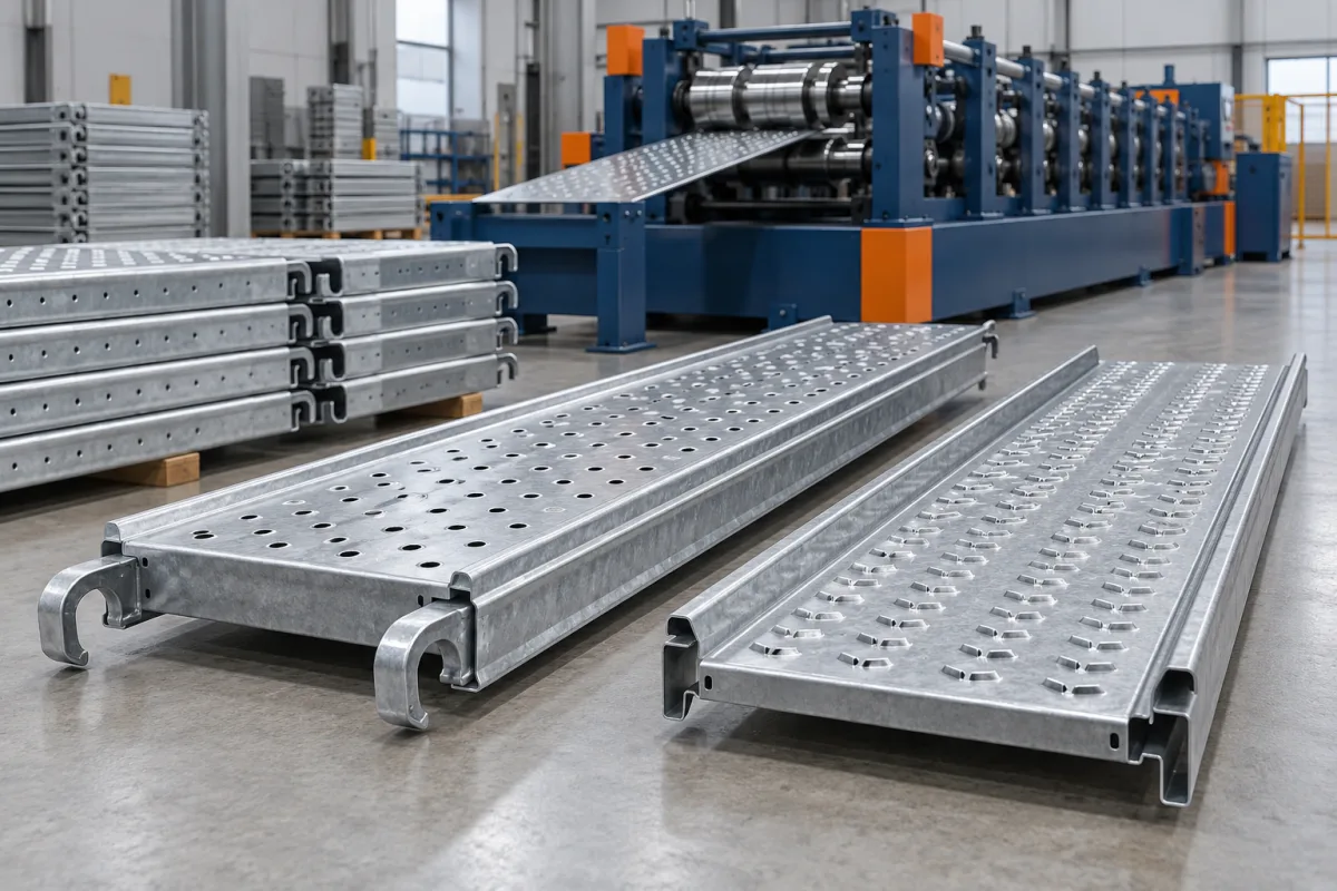
A platform plank or deck may need a formed section, specified surface features and end fittings. A ledger can have a different member construction and separately attached connectors. A frame combines several parts and requires its own assembly route. Define what the proposed line makes and what remains outside it.
- Scaffold Plank: review tread or perforation features, edges and end support.
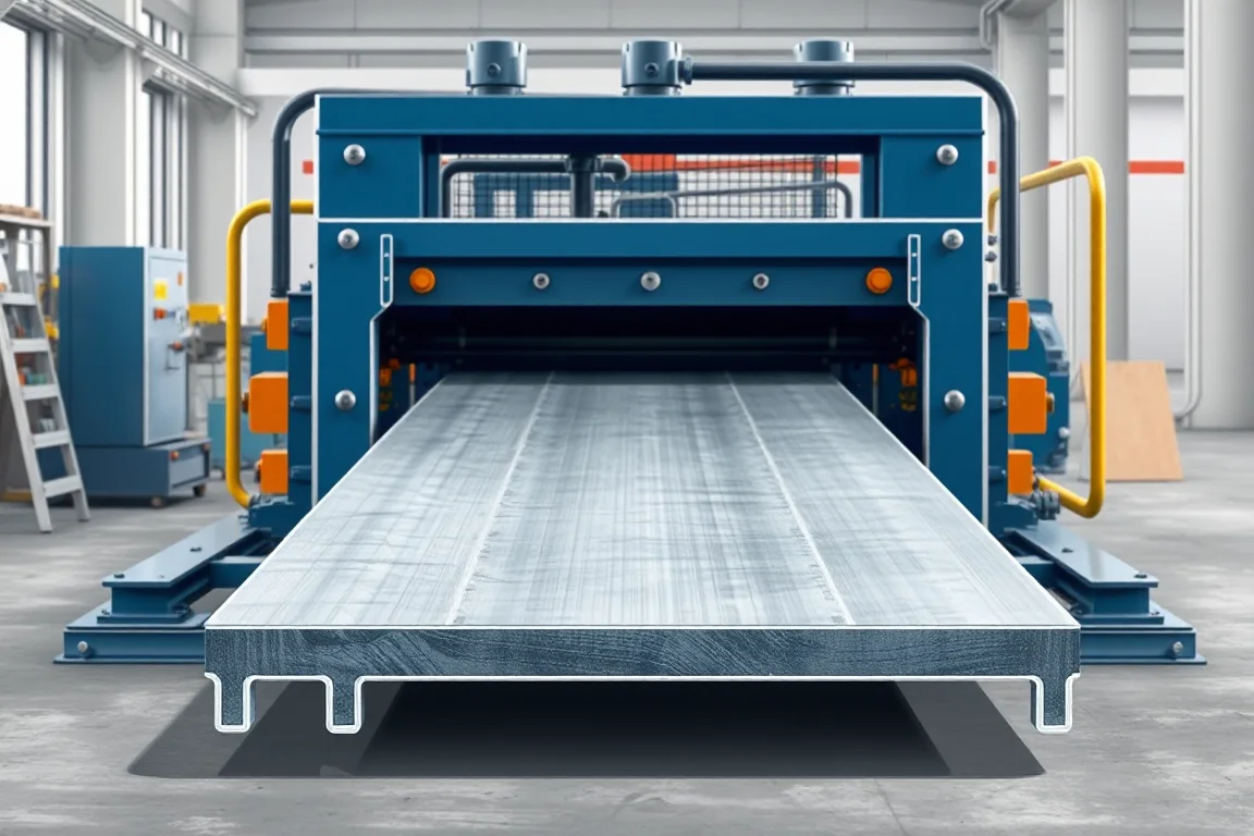
- Scaffolding Deck: connect the formed member with its hooks or retention arrangement.
- Ledger: establish the member construction and end-connector process first.
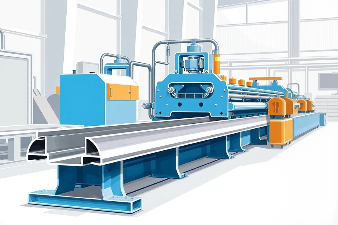
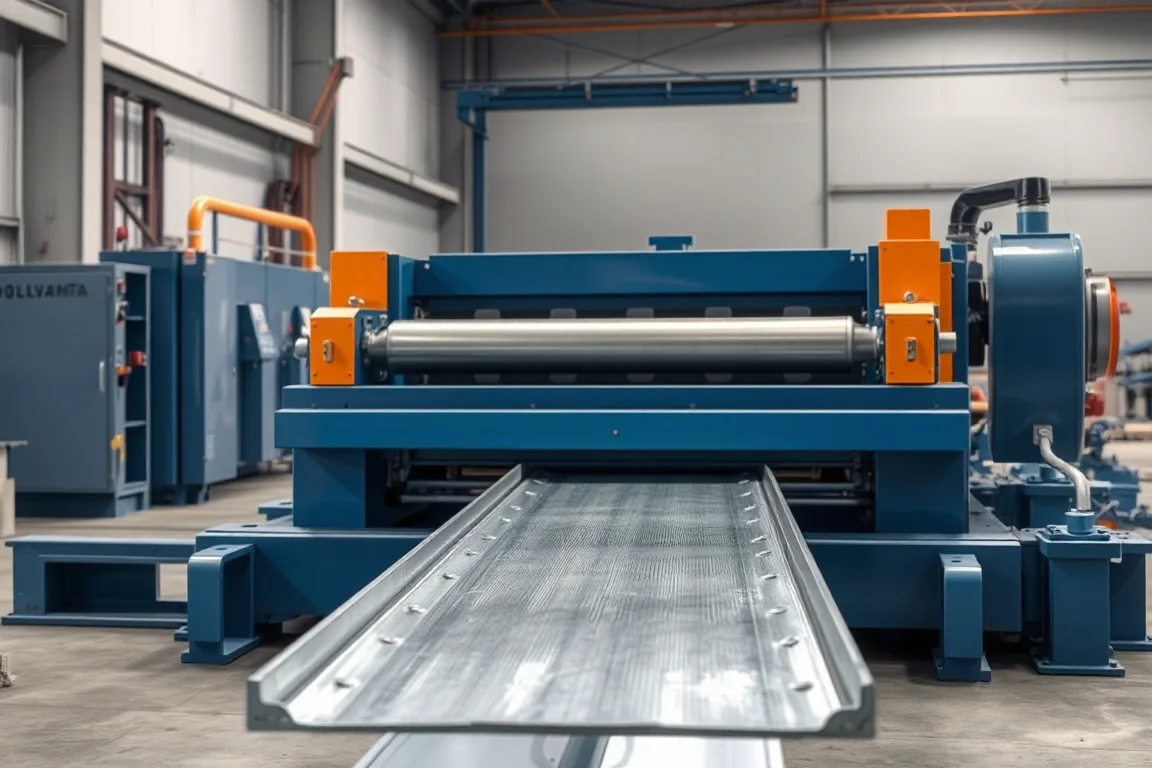
- Profile Line: map the specific component set and secondary operations.
Use the system's component drawings
Specify the section, material, ends and connection features from the intended scaffold design. A similar-looking connector or member should not be assumed compatible. The equipment needs a clear manufacturing target and a defined acceptance method.
For platforms, show how the component seats and is retained. For ledgers and frame members, identify joining and connection datums. A loose formed section does not demonstrate the completed component's interface.
Coordinate surface features and end fabrication
Perforation or specified anti-slip features need a controlled pattern and a relationship to bends and cut ends. Identify which operations are in-line and which use separate equipment. End hooks, brackets or connectors may introduce additional tooling, joining and inspection.
Keep these obligations visible in the quotation. A former producing the main section cannot be compared directly with a package that also supplies completed, identified components unless their scopes are normalized.
Review material and the finished processing route
State grade, thickness and coating requirements for each part. Inspect the component after the operations relevant to its supplied condition. Material substitution is not merely a machine adjustment when the component belongs to a controlled structural system.
Retain production-intent samples and material identity during trials. Evaluate edge condition, feature quality and any distortion introduced by later joining. This helps distinguish a forming issue from a fabrication or handling problem.
Check assembly without hiding deviations
Trial the intended mating components and support arrangement. Inspect the completed platform or member rather than only its central section. Record any need for unplanned reshaping or hole modification; making a display sample fit does not establish reproducible manufacture.
Scaffold loading and system approval depend on the defined design and relevant validation. A machine trial establishes a manufacturing result, not a blanket performance rating. Follow the responsible design process for deviations or substitutions.
Compare accepted finished components
Measure output with the required surface features, ends and joining complete. Different scaffold products have different bottlenecks, so formed metres alone are not a common finished-output measure. Include identification and normal packaging in the production boundary.
Prepare component and assembly drawings, material specifications, feature patterns and expected orders. The detailed pages below help distinguish suitable roll-forming tasks from the broader tube, connector and fabrication processes needed for a complete scaffold product range.
Continue your research
- Scaffold Plank Roll Forming Machine
- Scaffolding Deck Roll Forming Machine
- Scaffold Ledger Roll Forming Machine
- Scaffold Profile Roll Forming Line
- Ringlock Scaffold Ledger Roll Forming Machine
- Cuplock Scaffold Ledger Roll Forming Machine
- Scaffold Frame Profile Roll Forming Machine
- Scaffold Toe Board Roll Forming Machine
- How Scaffolding roll forming machine Works
- How To Choose a Scaffolding roll forming machine
- Scaffolding roll forming machine Price: What Affects the Cost?
- Materials and Thickness for Scaffolding roll forming machine
- Production Speed and Output of Scaffolding roll forming machine
- Roller, Tooling and Forming Design for Scaffolding roll forming machine
- Common Defects and Troubleshooting for Scaffolding roll forming machine