
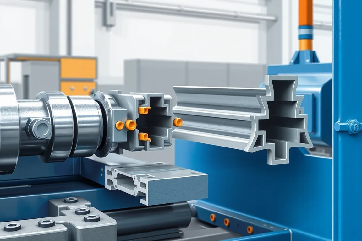
Roller and tooling design is the engineering core of a scaffolding roll forming machine. It defines how flat strip becomes a ribbed plank, a toe board or an open channel, and how that formed section meets hooks, end plates or support interfaces. The design is not a set of roll profiles alone: it links punch and emboss tooling, forming stands, cutoff tooling and downstream joining. Buyers who treat roll count as a quality indicator overlook the decisions that actually determine whether the finished component fits the approved scaffold-system drawing.
Start from the component drawing, not the machine category
A scaffold plank, toe board and ledger perform different functions. A plank needs a walking surface, ribs for stiffness and an anti-slip pattern. A toe board needs a defined upstand and fixing detail. A ledger typically needs a closed profile and welded end fittings. Roll forming is well suited to open sheet sections such as planks and channels, while a conventional tubular ledger may require tube production and separate joining equipment. The roller tooling design must begin with the functional geometry and mating parts, not with a generic machine label.
Begin with the approved scaffold-system drawing. Identify the walking surface, rib height and spacing, attachment interfaces and any end features. These dimensions drive the number of forming stations, the sequence of bends and the location of punch or emboss operations. Ringlock and cuplock are connection systems, not evidence that a ledger is made on a sheet-profile roll former. Confirm whether the component is an open section, a closed tube or a fabricated assembly before evaluating tooling.
How the forming sequence develops the section
Roll forming develops a bend gradually across stations. Each pass adds a controlled amount of deformation so the strip reaches the final shape without excessive local strain, twist or edge wave. The sequence usually begins with guide and entry rolls that locate the strip, followed by initial bend stations, intermediate forming stations, finishing stations and a cutoff. Anti-slip punching or embossing should be coordinated with this sequence because the pattern may be easier to produce while the strip is flat or at a specific stage before the section closes.
The interfaces matter as much as the roll contours. Guide rolls control lateral position and prevent the strip from wandering. Forming rolls impose the bend angle. Support and side rolls help contain the section as it develops. Cutoff tooling must match the finished profile so the cut end is clean and repeatable. If hooks or end plates are required, they may be produced by separate manufacturing and joining equipment, such as presses, welding fixtures or fastening stations. The roller tooling design should define how the formed section transfers to those operations without losing datum reference.
Why a roll count alone does not demonstrate quality
A higher roll count can suggest more gradual forming, but it does not prove that the bends develop correctly, that the strip is located consistently or that springback is managed. A lower roll count may be adequate for a simple open section, while a complex ribbed plank with an anti-slip pattern may need more stations and additional tooling. The useful question is not how many rolls, but how the forming design controls material flow, bend progression and section tolerance.
Springback is the elastic recovery of the strip after it leaves a forming roll. Tooling design addresses it through overbend, roll pressure distribution and station spacing, but the correct approach depends on material grade, thickness and yield behaviour. A design that works for one structural steel grade may not suit another. The tooling should account for material variation and provide access to the final section for inspection and adjustment.
Tooling interfaces: punch, emboss, cutoff and joining
Punch and emboss tooling creates holes, slots or raised patterns. Its position in the line affects strip handling and tool access. If the pattern is produced before forming, the strip is flat and easier to locate, but subsequent forming may distort the pattern. If it is produced after forming, the tooling must follow the curved section. The design should define the datum, the order of operations and how the pattern aligns with the final component.
Cutoff tooling determines end quality and length repeatability. A profile-supported cutoff uses a die or blade shaped to the section. The design should confirm the supported cut length, the end condition and any secondary operations such as deburring or end forming. When hooks or end plates are joined, the interface between the formed section and the joining equipment must be controlled. Inspection of the walking surface, ribs and attachment interfaces belongs to the finished component, not to a formed sample alone.
Material, thickness and forming behaviour
The buyer specifies the base-metal thickness and grade, and the operating range requires supplier verification. Material properties influence bend radius, springback, edge stretch and the risk of cracking. A tooling design that assumes one thickness and grade may not tolerate a wider range without adjustment. The practical approach is to define the expected material envelope and ask how the forming design accommodates it.
Surface finish and joining procedure also affect tooling. A coated or galvanized strip may require different roll surface treatment or handling to avoid marking. Welding or fastening procedures for hooks and end plates may impose heat input or clearance requirements that influence the formed section. These are component-production decisions, separate from assembly, certification and in-service performance. Load and slip requirements apply to the finished component and system, and they cannot be inferred from a formed sample alone.
Comparing tooling alternatives and trade-offs
When evaluating roller tooling design, compare the forming strategy rather than a single machine specification. One alternative is a dedicated tooling set for a single plank profile, which can optimise station count, bend sequence and punch position for that component. Another is a modular or adjustable tooling approach intended to cover several profiles or thicknesses. Dedicated tooling can simplify setup and repeatability, while modular tooling may reduce changeover time but can introduce more adjustment points and require tighter documentation.
A second trade-off is between integrated and separate operations. Integrated punch, emboss and cutoff tooling reduces handling and floor space, but may complicate access and maintenance. Separate operations can be simpler to service and adapt, but add transfer steps and possible datum loss. A third comparison is between roll-formed open sections and fabricated assemblies. Roll forming is efficient for long, uniform sheet sections, while a tubular ledger with welded end fittings may be better served by tube production and welding. The correct choice depends on the functional geometry and the intended interface.
Practical acceptance evidence for tooling and components
Acceptance should be tied to the agreed material and profile extremes. Inspect the walking surface, ribs and attachment interfaces against the approved drawing. Check that the formed section matches the mating parts. Review punch and cutoff tooling together with the roll tools, because a correct roll contour can still produce a poor component if the cutoff or punch alignment is wrong. Verify tool changes using the agreed material and profile extremes, and confirm that the setup is repeatable without undocumented adjustment.
Keep the accepted setup and tool identification together so production does not depend on an individual operator's memory. A tooling record should describe the roll set, the station sequence, the punch and cutoff configuration and the material range. This record supports troubleshooting and changeover. It also separates component production from assembly, certification and in-service performance, which are evaluated on the finished system.
Checklist for reviewing a roller tooling design
- Identify functional dimensions and mating parts from the approved scaffold-system drawing.
- Confirm whether the component is an open sheet section, a closed tube or a fabricated assembly.
- Review the forming sequence, including guide rolls, bend progression and finishing stations.
- Review punch and cutoff tooling together with the roll tools.
- Ask how bends develop, which surfaces locate the strip and how springback is addressed.
- Verify tool changes using the agreed material and profile extremes.
- Define the material envelope, including grade and thickness range, for supplier verification.
- Coordinate anti-slip punching or embossing with the forming sequence.
- Confirm how hooks and end plates are manufactured and joined.
- Keep the accepted setup and tool identification together.
FAQ: roller tooling design for scaffolding roll forming
How many forming stations are needed for a scaffold plank?
The number of stations depends on the rib geometry, the anti-slip pattern, the material thickness and the required section tolerance. A simple open channel may need fewer stations, while a ribbed plank with a patterned walking surface may need more. The design should show how each bend develops and how the strip is located. A roll count without a forming design does not demonstrate quality.
Can one tooling set produce planks and ledgers?
Usually not, because a plank is an open sheet section and a ledger is often a closed tube. Roll forming is useful for some sheet sections, but a conventional tubular ledger may need tube production and welded end fittings. The tooling design should match the construction method. If the ledger is an open section, confirm the connection interface and whether it meets the approved system drawing.
How is springback controlled in the tooling design?
Springback is managed by overbend, roll pressure distribution and station spacing, but the correct combination depends on material grade, thickness and yield behaviour. The tooling should account for material variation and allow access to the final section. The design should state how springback is addressed for the agreed material range rather than assuming a single grade.
Where should anti-slip embossing be placed in the line?
Anti-slip punching or embossing should be coordinated with the forming sequence. If the pattern is produced while the strip is flat, locating is easier, but later forming may distort it. If it is produced after forming, the tooling must follow the section. The design should define the datum and the order of operations so the pattern aligns with the finished walking surface.
What should be checked before accepting a tooling setup?
Inspect the walking surface, ribs and attachment interfaces against the approved drawing. Review punch and cutoff tooling together with the roll tools. Verify tool changes using the agreed material and profile extremes. Confirm that the cut end is clean and repeatable. Keep the accepted setup and tool identification together so production does not depend on an undocumented adjustment.
Do load and slip requirements apply to the formed sample?
Load and slip requirements apply to the finished component and system, and they cannot be inferred from a formed sample alone. The formed section must meet the drawing, but certification and in-service performance involve the assembled scaffold system. Component production, assembly and certification are separate stages, each with its own evidence.
Common symptoms and diagnostic evidence in tooling
Twist, edge wave or dimensional drift usually points to uneven bend progression, incorrect guide roll location or material variation. Poor cutoff quality may indicate a mismatch between the cutoff tool and the formed profile. Punch misalignment may appear as an offset pattern or distorted holes. When diagnosing these symptoms, review the setup record, the material certificate and the tool identification. Compare the formed section to the approved drawing at the mating interfaces. Avoid adjusting moving machinery while it is running; use the documented setup and inspection points to gather evidence before any change.
Continue your research
- Scaffolding Roll Forming Machines
- Scaffold Plank Roll Forming Machine
- Scaffolding Deck Roll Forming Machine
- Ringlock Scaffold Ledger Roll Forming Machine
- Cuplock Scaffold Ledger Roll Forming Machine
- Scaffold Frame Profile Roll Forming Machine
- How Scaffolding roll forming machine Works
- How To Choose a Scaffolding roll forming machine
- Scaffolding roll forming machine Price: What Affects the Cost?