
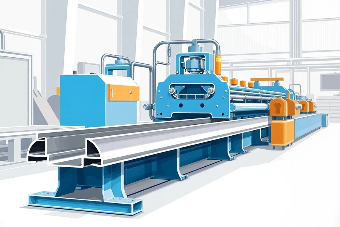
A scaffold ledger is a horizontal member that ties standards together and carries plank or deck loads into the vertical frame. In many scaffold systems the ledger is a tubular member with welded connection fittings, such as wedge, cup or rosette interfaces. That construction starts from tube, not from coil. A sheet-profile roll forming machine can be the correct route only when the approved scaffold-system drawing calls for a formed sheet section as the ledger. This equipment category therefore sits close to, but is not identical to, plank formers, deck formers and general scaffold profile lines. The decision starts with the drawing and the connection method, not with the machine name.
This article covers the exact finished profile, the interfaces that must be formed or added, the production route, tooling alternatives, separate operations, changeovers, inspection and accepted output. It is written for readers who need to judge whether a scaffold ledger roll forming machine fits an approved ledger design, and how to describe that fit in a quotation and acceptance plan.
What the finished ledger profile actually is
The finished profile is the cross-section the approved drawing defines. It may be a closed tube, an open channel, a lipped or ribbed sheet section, or another shape. A scaffold ledger roll forming machine forms from coil or strip; it builds the cross-section progressively through a series of roll passes. The profile can include a flat web, edge flanges, stiffening ribs and a return lip. The forming sequence must bend the material without thinning, cracking or distorting the intended section.
If the ledger is tubular, roll forming from strip is not the usual route. Tube is made by other processes and then cut, drilled, formed or welded. A sheet-profile former may be inappropriate unless the approved design specifically uses a formed sheet section. This distinction matters because a machine sold as a scaffold ledger roll forming machine may actually form a plank or a deck panel. Those are different products with different walking surfaces and different load paths. The forming line must be selected for the ledger section on the drawing.
The profile also defines where the connection interfaces sit. Hooks, end plates, spigots and wedge pockets are not incidental; they transfer load into the next member. Their position, thickness and weld or fixing detail come from the system design. A roll formed section that matches the outside shape but not the interface positions is not an acceptable ledger. Establish the ledger construction first, then decide whether a sheet-profile former belongs in the route.
Interfaces: hooks, end plates and support details
The ledger interfaces are the features that connect it to standards, transoms and other ledgers. Common examples include wedge hooks, cup or rosette heads, end plates with holes, and support seats. Some designs form part of the interface in the sheet section itself; others weld or rivet a separate fitting to the formed member. The exact interface is a drawing requirement, not a machine setting.
From a production viewpoint, interfaces create three questions. First, can the interface be formed in the same progressive pass as the main section, or must it be added later? Second, does the interface need a hole, slot or emboss that requires punch tooling in the line? Third, does joining the interface change the material properties or the finish enough to require a separate operation? Welding, for example, may require cleaning and a coating step afterward. If galvanizing follows welding, the process must account for the full finished component, including drainage and venting. Those choices sit outside the forming machine itself.
Interface position is also an inspection item. A formed sample can show that the section shape is close, but it cannot by itself prove that the assembled ledger meets load and slip requirements. Those requirements apply to the finished component and the system. Inspection must therefore cover the formed body, the added fittings and the assembled interface.
The production route from coil to inspected ledger
A typical sheet-based route is: punch or emboss, then plank or channel forming, then cutoff, then end fitting or joining, then inspection. Each step has its own tooling and its own failure modes. Punching or embossing creates holes, slots, anti-slip features or stiffening marks before or during forming. Forming builds the cross-section. Cutoff separates the finished length and defines the end quality. End fitting or joining adds the connection interfaces. Inspection confirms the finished component.
The order can change with the design. Some features are easier to punch before forming because the strip is flat and access is simple. Others are better formed first and punched in place. Some sections need a secondary press or drilling station after cutoff. The route must be written for the actual ledger, not copied from a related product.
Cutoff is often underestimated. The cutoff method must suit the formed profile, the cut length, the end squareness and any secondary operations at the ends. A profile-supported cutoff may be needed where the section is open or asymmetric. If the ends will be welded to fittings, the cut face and any burr affect fit-up. The quotation should state who provides the cutoff tooling and how end quality is checked.
Tooling alternatives for forming and cutting
Roll tooling design is driven by the section. A simple symmetrical channel may use a straightforward pass progression. A lipped or ribbed profile with tight radii and a wide flat web needs more passes, more careful bend sequencing and sometimes a different material grade to avoid cracking. The number of passes is not a universal rating; it follows from the section geometry and the specified material.
There are also alternative forming concepts. A conventional roll former uses driven shafts and matching rolls. A cassette or quick-change roll set can reduce changeover time when the line runs more than one ledger profile. A combined punch-and-form line places the punching station in line with the rolls. A separate press and former arrangement can suit lower volume or more variable work. Each alternative changes capital cost, floor space, setup time and the skill needed to run the line.
Cutoff alternatives include shear, saw and punch-type cutters. Shear is common for thin sheet sections; saw can suit thicker or harder material and can leave a different end finish. The choice must be confirmed against the profile and the end use. For tubular ledgers, the relevant tooling is tube cutting, end forming and welding fixtures, not roll forming passes.
Operations that remain outside the forming machine
The forming machine rarely produces a finished scaffold ledger on its own. If the design uses welded end fittings, the route needs cutting, fixturing, welding, cleaning and coating equipment. If the design uses bolted or riveted interfaces, it needs drilling, riveting or fastening stations, plus the associated fixtures and gauges. Handling and packaging also sit outside the former.
This separation matters for output planning. Count finished inspected ledgers including end attachments. A high forming speed does not help if joining and inspection are the production constraint. The line may form quickly and then wait for welding, coating or final checking. A quotation that covers only the former can leave the buyer without the equipment that actually completes the part.
Coating is another separate operation. If the finished ledger is galvanized, painted or otherwise protected, the process must account for the full component. Coating after welding can change dimensions slightly, and it can affect interface fit. The inspection plan should include the coated condition where the drawing requires it.
Changeovers between ledger profiles and lengths
Changeover is the work needed to move from one profile or cut length to another. On a roll former it can include changing rolls or cassettes, adjusting pass positions, changing punch tooling, resetting the cutoff length and re-establishing the first-off quality. On a tube-based line it includes changing fixtures, stops and welding settings.
Changeover time is not a fixed machine rating. It depends on the number of driven stations, the tooling concept, the accessibility of adjustments and the skill of the operator. A line with quick-change cassettes may reduce setup time for multiple profiles. A dedicated single-profile line may have very little changeover but no flexibility.
Setup scrap is part of changeover. Each new setup produces first-off pieces that must be checked before steady production. The quotation and production plan should record the changeover steps, the setup scrap expected and the time needed for punching and unloading. That record lets the buyer compare lines on the basis of finished parts per shift, not forming speed alone.
Inspection and accepted output
Inspection should start with material identification. Record the grade, thickness and coating of the incoming coil or tube against the approved specification. Then inspect the formed profile: web flatness, rib shape, flange angle, edge condition and overall section. Check the prepared lengths and end positions against the drawing. For assembled ledgers, inspect the fitted interfaces, weld or fixing quality and the agreed joining checks.
A first-off piece after each setup and a representative steady-production sample are both useful. The agreed gauges should be used, and the results recorded. A formed sample alone does not prove load and slip performance; those requirements apply to the finished component and the system. Acceptance criteria should be written for the actual profile and material, not for a demonstration substitute. Run the agreed material and profile before approving the line.
Accepted output is the count of finished inspected ledgers that meet the drawing and the agreed checks. It should include end attachments and normal receiving and storage of finished ledgers in the workflow. The forming operation alone is not the full production cycle, so accepted output must be defined at the end of the complete route.
Practical checklist for evaluating a proposed line
- Confirm the approved ledger drawing: is it a tubular member, a sheet section or another construction?
- List every interface: hooks, end plates, spigots, wedge pockets and support details.
- State the material grade, thickness and coating for the finished component.
- Write the production route: punch or emboss, forming, cutoff, end fitting or joining, inspection.
- Confirm cutoff requirements: profile support, cut lengths, end quality and secondary operations.
- Decide whether interfaces are formed in line or added by separate equipment.
- State the electrical supply: voltage, frequency and phase. Installed power needs a confirmed equipment schedule.
- Define accepted output per shift with the actual profile and material.
- Record changeover steps, setup scrap and unloading time.
- Agree inspection items: material identification, prepared lengths, end positions and joining checks.
- Include end-fitting equipment, joining fixtures, handling and verification in the quotation scope.
- Compare the written equipment scope with every secondary operation needed for a finished part.
Comparing alternatives without a universal answer
Three broad alternatives exist. First, a dedicated roll forming line for a sheet-based ledger profile. It can give consistent section shape and good throughput for one design, but it may not be flexible and it does not solve interface joining. Second, a tube-based route with cutting, end forming and welding fixtures. It suits tubular ledgers with welded fittings and uses different equipment. Third, a hybrid or flexible line that combines forming with separate joining stations. It can adapt to more than one design but usually costs more and needs more setup discipline.
There is no universal best choice. The correct route follows from the approved ledger construction, the material and the required interfaces. A plank former presented as a complete scaffold manufacturing plant is a scoping error. A general scaffold profile line may form a related section but not the ledger interface. Buyers should compare alternatives on finished inspected ledgers per shift, changeover effort, secondary operations and verification requirements, not on a single headline speed.
FAQ
Can a scaffold ledger roll forming machine make a tubular ledger?
Generally no. A roll forming machine forms from coil or strip into a sheet cross-section. A tubular ledger is made from tube, then cut, drilled, formed or welded. Unless the approved drawing specifically uses a formed sheet section, a sheet-profile former is the wrong starting point. The correct route is tube production or tube purchase plus end fitting and joining.
Where do hooks and end plates get made?
They are usually separate manufactured items joined to the formed or tubular member. The joining method comes from the system design: welding, bolting, riveting or another fixing. The forming machine may punch or emboss some interface features, but the fitting itself and its joining fixture are separate equipment and separate scope items.
How do I define accepted output for a ledger line?
Count finished inspected ledgers that meet the drawing, including end attachments. Define the profile, material, cut length, interface checks and joining inspection. Include changeover steps, setup scrap, punching and unloading time. Accepted output at the end of the complete route is more useful than forming speed alone.
What should the quotation include beyond the forming machine?
It should include end-fitting equipment, joining fixtures, handling, coating where required and verification requirements. It should state the electrical supply and the confirmed equipment schedule. It should identify any secondary operations needed for a finished part and who provides the tooling for each.
What is inspected on a finished ledger?
Inspect material identification, the formed profile, prepared lengths and end positions, then the fitted interfaces and joining quality. Use the agreed gauges and record results. A formed sample does not prove load and slip performance, because those requirements apply to the finished component and the system.

Continue your research
- Scaffolding Roll Forming Machines
- Scaffold Plank Roll Forming Machine
- Scaffolding Deck Roll Forming Machine
- Ringlock Scaffold Ledger Roll Forming Machine
- Cuplock Scaffold Ledger Roll Forming Machine
- Scaffold Frame Profile Roll Forming Machine
- How Scaffolding roll forming machine Works
- How To Choose a Scaffolding roll forming machine
- Scaffolding roll forming machine Price: What Affects the Cost?
Configuration & specification inputs
Match the configuration to your section drawing, material and production requirements.
| Parameter | Requirement / confirmation needed |
|---|---|
| Profile geometry | Common scaffold ledgers use tubular members and welded connection fittings. Establish the ledger construction first; a sheet-profile former may be inappropriate unless the approved design specifically uses such a section. |
| Material | Specified structural steel with the required finish and joining procedure |
| Thickness & grade | Buyer to specify base-metal thickness and grade; operating range requires supplier verification. |
| Process route | Punch/emboss → plank or channel forming → cutoff → end fitting/joining → inspection |
| Cutting | Confirm profile-supported cutoff, cut lengths, end quality and any secondary operations. |
| Output | Define accepted output per shift with the actual profile and material. |
| Electrical supply | Buyer to state voltage / frequency / phase. Installed power requires a confirmed equipment schedule. |
| Acceptance | Record material identification, prepared lengths, end positions and the agreed joining inspections. Include normal receiving and storage of finished ledgers in the workflow. Do not treat the forming operation alone as the full production cycle. |