
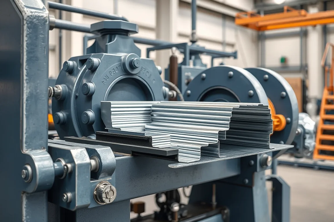
Roller and tooling design is the engineering link between a gutter or downpipe drawing and a machine that can produce it repeatedly. It decides how the strip is guided, how bends develop, how the seam closes and how the finished section leaves the cutoff. A roll count alone does not demonstrate quality. What matters is whether the forming design matches the profile, the material and the intended joints.
What roller and tooling design actually controls
Roller tooling does more than bend metal. It locates the strip, sets the order of bend development, controls the position of the neutral axis, manages springback and shapes the final mating surfaces. Cutting and punching tools are part of the same system because a profile that forms well can still be spoiled by a cutoff that crushes it or a punch that distorts the bead.
For gutters, the critical features are usually the open cross-section, the front bead or hem, the back flange and the bottom radius. For downpipes, the closed seam and the roundness or ovality of the section are more important. These are different forming problems, so a single tooling set rarely serves both well without a defined changeover.
Why functional geometry comes before roll count
Start with the complete roof drainage detail: the gutter cross-section, the bead or hem, the downpipe seam and the outlet interface. A style name such as K-style or ogee can overlap between suppliers, so a dimensioned sketch and a cross-section drawing are more reliable than a label. The forming design should be derived from those dimensions, not from a generic profile family.
The same principle applies to mating parts. Outlets, elbows, brackets and end caps all interact with the formed section. If the tooling does not hold the interface dimensions, the joints will not fit even when the gutter looks correct in isolation. Drainage design itself depends on the building and local requirements, which the gutter former does not establish.
How the forming sequence develops, station by station
A gutter line typically begins with coil payoff, then progresses through a series of forming stations. Early passes may pre-bend edges or establish a reference flat. Middle passes develop the main bends gradually, and later passes close the bead or hem and set the final section. The sequence matters because each pass changes the strip's stress state and its position relative to the next roller.
Each station has an interface with the previous and next one: the strip must enter with the right orientation, be located on a consistent surface and leave without twist. If one station takes too much bend, the following station may fight it. If it takes too little, later stations may not close the profile. The design should show how bends develop and which surfaces locate the strip at each stage.
Downpipe forming is usually a closed-seam process. The strip is progressively curled, the seam is brought together and closed, and the roundness is set. Elbow production is normally a separate secondary forming operation because the geometry changes direction. A downpipe former does not necessarily make elbows, so that process needs its own review.
Material behaviour and springback considerations
Coated steel and aluminum behave differently in forming. Coating type, base-metal grade, thickness and temper all affect how much the strip springs back after each bend. The tooling design should account for material variation rather than assume a single response. Copper requires its own process review because its forming behaviour and surface sensitivity differ from coated steel and aluminum.
Springback is managed through overbend, station spacing, roller pressure and the order of operations. Overbend can be built into the roller geometry, but it must be balanced against the risk of marking or thinning the material. The design should also consider access to the final section, because some profiles are difficult to adjust once closed.
Locating surfaces and strip guidance
Every forming line needs a consistent locating strategy. The strip should be guided by surfaces that are stable throughout the process, often the flat web or a controlled edge. If the locating surface changes from station to station, the profile can drift and the finished section may vary along the coil.
Guidance also affects straightness. A gutter that curves or twists after forming often reflects uneven strip entry, inconsistent locating or asymmetric bend loads. The tooling design should show how the strip is centred and how side loads are managed, especially where the profile is open and flexible.
Cutoff, punching and secondary operations
Cutoff tooling must support the profile rather than crush it. For open gutters, internal support or a shaped die can help maintain the cross-section during the cut. For closed downpipes, the cutoff should not distort the seam or roundness. The design should confirm profile-supported cutoff, cut lengths and end quality.
Punching or notching for outlets and brackets is often integrated with the line, but it can also be a separate operation. The tooling design should treat punching and cutoff together with the roll tools, because a hole or notch can change how the section behaves in later stations. Any secondary operation that bends or forms the profile, such as elbow making, should be reviewed as its own process.
Tool change strategy and setup discipline
Changeover is a design decision. Some lines use common shafts and swap roll sets; others use split rolls or adjustable stations. The choice affects setup time, repeatability and the risk of undocumented adjustments. A tooling design that requires frequent re-shimming or guessing is harder to keep consistent.
The design should also define tool identification. Keeping the accepted setup and tool identification together helps production remain repeatable. If a change is needed, it should be recorded against the tool set and the material used for verification.
How to compare tooling design alternatives
When comparing suppliers or tooling concepts, look at the engineering content rather than a list of features. A useful comparison covers the forming sequence, the locating strategy, how springback is addressed, how the cutoff supports the profile and how tool changes are managed.
- Fixed roll set: predictable for a single profile and material, but less flexible if the profile or thickness changes.
- Adjustable stations: more tolerant of material variation, but they can be misadjusted if the setup is not documented.
- Split rolls or common shafts: faster changeover, but the tooling must still hold the interface dimensions.
- Integrated punch and cutoff: fewer handling steps, but the tooling design must protect the formed section.
- Separate secondary forming: clearer process control for elbows or outlets, but it adds a handling and quality checkpoint.
The tradeoff is usually between flexibility and repeatability. A design that is easy to adjust may drift if the setup is not controlled. A design that is fixed may be very consistent but limited to the profile it was made for.
Acceptance checks and diagnostic evidence
Acceptance should be based on the agreed material and profile extremes. Inspect the bead or hem, straightness and joining fit. For downpipes, check the seam and the mating outlets or elbows. These checks show whether the tooling holds the functional geometry, not just whether the line runs.
If a defect appears, gather evidence before changing anything. Record the station where the deviation starts, the material batch, the strip position and the condition of the tooling. Symptoms such as twist, edge wave, seam opening or surface marking each point to different causes. For example, a seam that opens progressively may indicate insufficient closing pressure or a locating issue; a bead that cracks may point to material condition or excessive bend severity. Do not adjust moving machinery while it is running. Use the recorded evidence to decide whether the issue is in the forming design, the material or the setup.
Practical checklist for reviewing a tooling design
- Identify functional dimensions and mating parts, including outlets and elbows.
- Confirm the forming sequence and how bends develop at each station.
- Check which surfaces locate the strip and whether they remain consistent.
- Review how springback is addressed for the specified material and thickness.
- Verify that punch and cutoff tooling support the profile.
- Confirm tool change method and how settings are documented.
- Plan acceptance checks using the agreed material and profile extremes.
- Keep the accepted setup and tool identification together.
FAQ
Can one tooling set make both gutters and downpipes?
Generally no, because the forming problems differ. A gutter is an open section with a bead or hem, while a downpipe is a closed seam with different roundness and joining requirements. Some machines use interchangeable roll sets, but the tooling design still needs to be specific to each profile. A shared tooling set that compromises both is rarely the best choice unless the profiles are very similar.
Why does the finished gutter twist even when the rolls look aligned?
Twist can come from uneven strip entry, inconsistent locating surfaces or asymmetric bend loads across the line. It can also reflect material variation that the tooling was not designed to accommodate. Checking the station where the twist first appears, the strip position and the tooling condition gives more useful evidence than adjusting rolls at random.
How is springback handled in a gutter roll forming line?
Springback is handled through a combination of overbend in the roller geometry, station spacing and the order of bend development. The design should account for the specified material and thickness, because coated steel and aluminum respond differently. Overbend must be balanced against the risk of marking or thinning the material, especially at the bead or hem.
Does a higher roll count mean better tooling design?
A roll count alone does not demonstrate quality. More stations can distribute bend severity, but they also add cost and setup complexity. What matters is whether the forming sequence develops the profile without overstressing the material, whether the strip is located consistently and whether the cutoff and punch tools support the section. The design should explain how bends develop, not just how many stations exist.
What should be inspected at acceptance?
Inspect the bead or hem, straightness and joining fit. For downpipes, check the seam and the mating outlets or elbows. Use the agreed material and profile extremes so the inspection reflects the intended production range. These checks show whether the tooling holds the functional geometry that matters for installation and drainage.
Can the same line make elbows as well as downpipes?
Elbow production normally requires a defined secondary forming process because the geometry changes direction. A downpipe former does not necessarily make elbows, so the elbow process should be reviewed separately for tooling, handling and quality checks. Treating it as a separate operation makes the process control clearer.
Continue your research
- Gutter & Downspout Roll Forming Machines
- Gutter Roll Forming Machine
- Downspout Roll Forming Machine
- K Style Gutter Roll Forming Machine
- Half Round Gutter Roll Forming Machine
- Box Gutter Roll Forming Machine
- How Gutter roll forming machine Works
- How To Choose a Gutter roll forming machine
- Gutter roll forming machine Price: What Affects the Cost?