
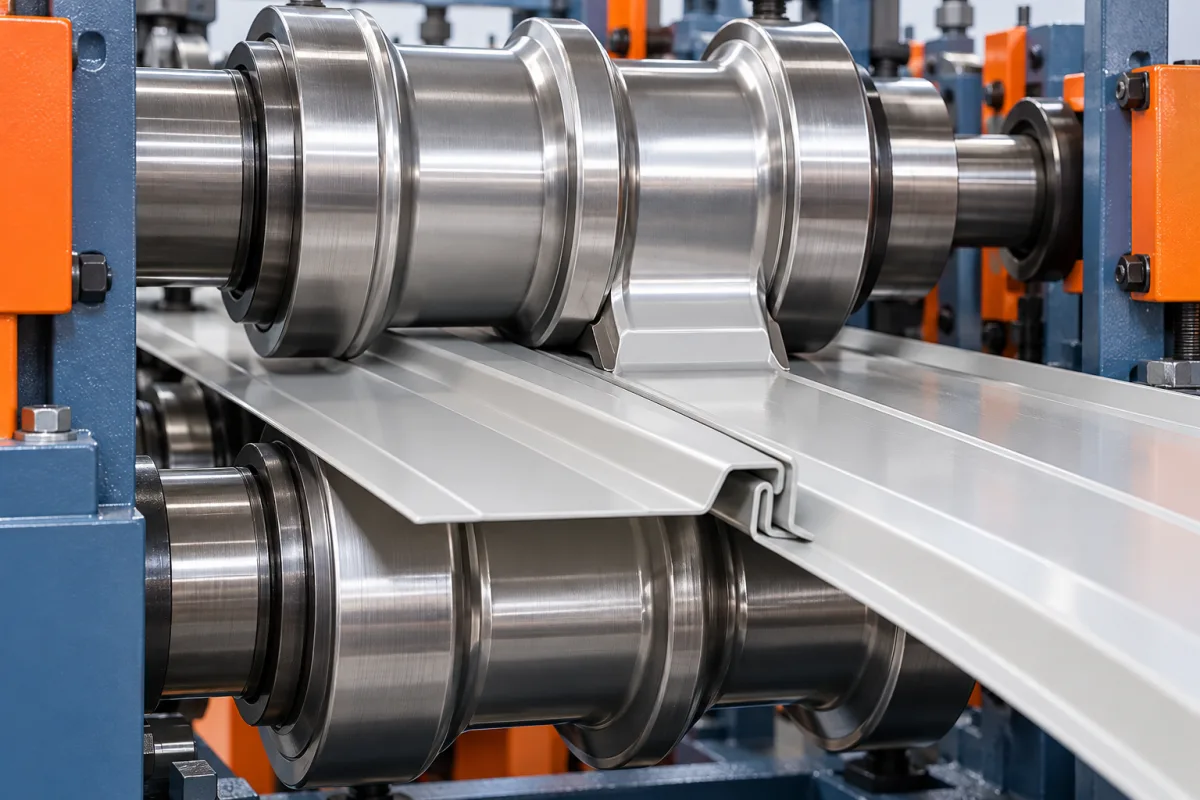
Wall cladding tooling is designed around two connected objectives: a repeatable visible face and a functional edge assembly. The face may be broad and visually sensitive, while the returns or fixing details demand controlled geometry. Reviewing both together is more useful than judging a tool set by the number of rolls or the appearance of a short sample.
Establish the complete section and assembly references
Provide a controlled transverse drawing showing the face, returns, fixing flange or clip interface, effective cover and reveal. Include an assembled joint drawing. The tools need a precise target that goes beyond the overall width and nominal depth of a panel.
Identify which dimensions govern fit and which govern appearance. Their inspection methods may differ. A return that is measured from the wrong datum can appear acceptable while preventing adjacent panels from engaging consistently.
Review the forming path around wide faces
A cladding section reaches its final shape through intermediate developments. Ask the tooling specialist to explain how the proposed route manages the relationship between the face and edge features in the specified material. The final silhouette alone does not describe that process.
Keep design discussions tied to the actual section. A broad smooth face, a ribbed siding face and an interlocking narrow panel can require different priorities. Avoid requesting a universal pass arrangement simply because another machine uses it for a different product.
Concealed returns need their mating components
If the panel uses a separate clip or another attachment, supply that component during development. The geometry must be evaluated in its assembled condition, not inferred from a nominal clip height or a photograph. The installation sequence should be available to the tooling and inspection teams.
Record the engagement observations during trials. Excessive resistance, local modification or inconsistent alignment can be hidden by a final assembled photograph. A repeatable joint demonstration provides stronger evidence than one successful short sample.
Distinguish width adjustment from profile redesign
A machine may change a selected face dimension while retaining one edge system. That does not mean it can produce any reveal, return or fixing arrangement. Request a matrix identifying the combinations supported by adjustment and those requiring replacement tools.
For each required transition, identify guides, roll components, cutoff parts and setup references. Changes should be assessed through to an accepted product. This makes the practical tooling flexibility visible instead of leaving it hidden behind the word adjustable.
Account for material and finish during tool approval
Grade or alloy, thickness, width and surface system should be specified as combinations. The shape after bending and the appearance at contact areas can differ between materials. A tool set approved on one trial coil should not be treated as universally validated.
Include protective layers in the development discussion. If a finish or backing changes, determine whether another process review is required. Keep the approved material matrix associated with the tool revision so future production teams know what was actually demonstrated.
Coordinate holes, notches and cutting interfaces
Repeated fixing features need a defined location and production method. Their relationship to the formed joint can affect assembly. State whether features are created before, during or after forming and how their positions are checked on the finished panel.
Cutting components also need to preserve the functional returns at both ends. A tool review limited to the mill can miss this interface. Ask for complete panels made through the proposed cutoff and handling route, not only sections removed from the middle of a sample.
Make appearance trials repeatable
Agree the support, viewing and lighting conditions used to judge the face. Include representative lengths and normal discharge. These conditions help distinguish actual differences from changes in how the same panel is presented.
Retain a documented reference assembly with its material and setup identity. It should not be an unexplained showroom sample. When a later batch looks different, the team needs enough information to compare product, material, tooling and handling rather than relying on memory.
Verify return-to-profile repeatability
A flexible line should demonstrate a meaningful configuration change and recovery of a previous accepted profile. Inspect the joint, face and cut ends after the return. This checks whether setup references support repeatable production rather than only a one-time demonstration.
- Identify the initial approved profile and coil.
- Run and inspect representative panels.
- Perform the required configuration change.
- Approve the second product using its own references.
- Return to the first setup and verify the recovered result.
Control revisions across the facade system
When a legacy sample is used as the starting point, first confirm that it represents the desired current design. Wear, local repairs or unknown manufacturing history can make an old physical panel an unreliable sole master for new tooling.
A changed clip, return or reveal can affect the panel tools and other components. Treat it as a controlled product revision. Identify the drawings, tools, samples and installation references affected before mixing old and new parts in production.
This is especially important when small architectural adjustments accumulate across projects. A tool set should not gradually become an undocumented hybrid. Clear revision control can remain simple: the correct drawing, tool identity and approved sample need to agree.
Frequently asked cladding tooling questions
Does a smooth wide face require the same tools as a ribbed face?
Not necessarily. The complete geometry and material route must be reviewed. A visible face change can affect the development and should not be treated as an interchangeable decoration.
Can a clip be substituted after tool approval?
Only after the relevant compatibility review. Similar nominal dimensions do not prove that mating surfaces and installation behavior are equivalent. Use the approved component in acceptance trials.
Why are long samples requested for tool acceptance?
They reveal straightness, joint continuity, face appearance and handling effects that short coupons can miss. Combine them with precise section measurements rather than choosing one method alone.
What should be retained when a tool set is delivered?
Profile and joint drawings, tool identification, supported material combinations, setup references and representative acceptance records. Together these provide a practical basis for recovery, service and future changes.
Continue your research
- Wall Cladding Roll Forming Machines
- Wall Panel Roll Forming Machine
- Metal Siding Roll Forming Machine
- Box Profile Wall Panel Roll Forming Machine
- Corrugated Wall Cladding Roll Forming Machine
- Trapezoidal Wall Cladding Roll Forming Machine
- How Wall cladding roll forming machine Works
- How To Choose a Wall cladding roll forming machine
- Wall cladding roll forming machine Price: What Affects the Cost?