
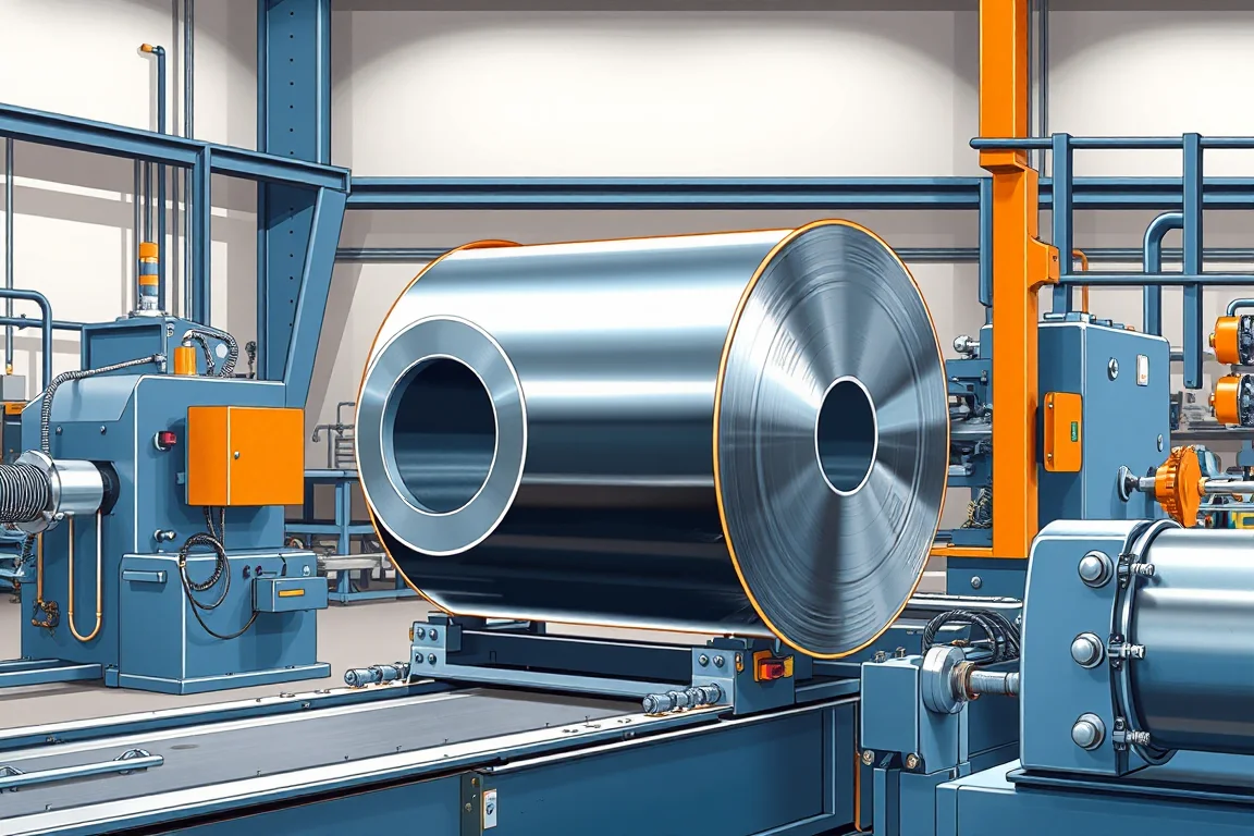
What a heavy gauge steel coil slitting line does
A heavy gauge steel coil slitting line converts a wide, thick master coil into multiple narrower coils by passing the strip through a set of circular knives. Unlike lighter slitting, the process must manage substantial coil mass, high separating forces, significant stored energy in the uncoiled strip and heavy finished coils. The line is not simply a single machine; it is an integrated arrangement of loading, payoff, slitting, tension and recoiling equipment with defined interfaces between each stage. The purpose is usually to feed a downstream forming, welding or blanking operation with strip widths that match a specific part or product. Because the material is thick and strong, the line's capacity must be expressed as a paired thickness-and-strength statement rather than a single maximum thickness figure. A grade with higher yield strength requires more force to shear and more torque to recoil, so the same nominal thickness may or may not be suitable. Buyers should provide base-metal thickness, grade and the intended operating range for supplier verification before any capacity claim is accepted.
Why heavy gauge differs from light-gauge slitting
Light-gauge slitting lines often run at high speed with modest tension and relatively simple recoiling. Heavy gauge changes the engineering priorities. The separating forces at the knife arbor are larger, so the arbor, housing and drive train need stiffness and bearing support appropriate to the duty. Tension control becomes more important because a heavy strip carries more kinetic energy and any tension loss can cause loose or telescoped coils. Scrap and edge trim are also heavier and more awkward to handle, so scrap chopping or winding equipment must be matched to the material. Finished coils are heavy, which affects recoiler design, coil car capacity and removal method. In practice, a heavy gauge slitting line is closer to a small processing plant than to a single slitting head, and the project scope should reflect that.
Component interfaces from coil to finished strip
The line begins with coil loading. A coil car or lifting arrangement positions the master coil on the payoff mandrel. The interface between the coil car and the mandrel includes alignment, centering and the ability to hold the coil during threading. The payoff then feeds strip into the line, often with a peeler or hold-down to control the leading end. The strip next passes through a slitting head where the knife setup determines the number and width of strips. After slitting, the strips separate and may pass through a tension device or a recoiler. Each interface has mechanical, electrical and control implications. For example, the recoiler must develop enough torque to pull the strip without slipping, and the tension system must coordinate with the payoff brake or drive. Scrap handling must be positioned so that edge trim does not interfere with strip travel. The layout should show which operations are included and how strip is threaded, because threading a heavy strip is a significant part of the operating cycle.
Process route options and how they differ
A heavy gauge slitting line can be configured in several ways. A basic slitting route includes payoff, slitting head, scrap handling and recoiler. If the strip needs improved flatness, a leveler may be placed before or after slitting, but leveling heavy material requires a separate capacity assessment. If the output is cut lengths rather than coils, a cut-to-length shear and stacker replace or supplement the recoiler. These are different production routes, not interchangeable modules. Slitting produces narrower coils; cut-to-length produces sheets or blanks. A combined line may include both, but then the control system must manage two distinct modes and the physical layout must allow strip to bypass one function. The choice depends on the downstream process. If the next operation consumes coil, a recoiling route is appropriate. If it consumes flat sheets, a cut-to-length route is more direct. Mixing the two on one line adds changeover steps and potential for setup error, so the decision should be based on the actual product mix and not on a desire for flexibility alone.
Drawing and material inputs that define the project
The starting point is a clear statement of coil width, thickness, mass, inside diameter and outside diameter, together with the required strip or blank dimensions. Thickness and width must be paired with grade and strength. Surface-sensitive material may need special contact surfaces, roll coverings or handling precautions to avoid marks and scratches. The buyer should specify the base-metal thickness and grade, and the operating range requires supplier verification. Incoming coil condition also matters: camber, crown, rust, scale and edge condition all affect slitting results. The acceptance criteria should define how incoming coil defects are distinguished from process-induced damage. If a defect appears after slitting, it is not automatically a line fault; the incoming coil may have had a condition that only became visible after the strip was separated. Documenting the incoming coil condition before processing helps separate the two causes.
Slitting head, knife setup and edge quality
The slitting head holds the knife arbors and spacers that determine strip width. Knife setup includes clearance, overlap and lateral adjustment, and these settings depend on thickness, grade and the required edge condition. For heavy gauge, the knife and spacer stack must be robust and the locking arrangement must resist the forces involved. Edge burr is a common acceptance check. A burr that is too large can affect downstream welding or forming, while an excessively rolled edge may indicate incorrect clearance or dull knives. The line should allow controlled knife changes with the equipment maker's procedures and qualified personnel. Stored-energy controls are important because the arbors and coils can retain energy after the drive is stopped. Tool changes should follow the equipment maker's procedures; this article does not describe adjustment steps for moving machinery. The practical point is that edge quality is a function of knife condition, setup and material, and it should be inspected on first-off and steady-production samples.
Recoiling, tension and finished coil handling
After slitting, each strip is recoiled to a specified coil inside diameter, outside diameter and weight. Tension control affects coil tightness, telescoping and edge alignment. A heavy gauge line may use a tension pad, a belt wrapper or a separate tension stand, depending on the material and the recoiler design. The recoiler must be matched to the strip tension and coil weight, and the coil car or removal equipment must be able to handle the finished coil without damaging it. Finished-coil movement is often underestimated in project planning. If the coil is too heavy for a forklift or too wide for a storage saddle, the line may produce good strip but create a handling problem. The layout and capacity review should include loading, restraint, payoff, slitting and removal, not only the slitting head itself. A maximum strip speed does not describe the full operating cycle; coil loading, threading, recoiling and bundle movement can dominate real production time.
Scrap and edge trim handling
Heavy gauge slitting produces edge trim and occasional scrap that must be collected and removed. The scrap handling method depends on strip width, thickness and the layout. Options include choppers, scrap winders or containers positioned below or beside the line. The interface between the scrap handling equipment and the slitting head must allow trim to exit freely without pulling on the strip or creating a safety hazard. Scrap removal should be included in the project scope because omitting it can make an otherwise complete line unworkable. The operator should not need to reach into the line to clear scrap while it is running; the design should provide a safe method for removal with the line stopped and energy isolated. This is a scope item to confirm, not a detail to resolve after installation.
Assembly boundaries, certification and in-service performance
A heavy gauge slitting line is assembled from several subsystems: payoff, slitting head, scrap handling, tension system, recoiler, controls and material handling. The assembly boundary defines which party is responsible for mechanical integration, alignment, electrical connection and commissioning. Certification and compliance requirements depend on the destination market and the user's own safety obligations; they are not inherent to the machine description. In-service performance depends on the actual material, the operating discipline and maintenance. A line that performs well on a demonstration coil may behave differently when production material varies. For this reason, acceptance should be based on agreed material and profile, not on an easier demonstration substitute. The buyer should define accepted output per shift with the actual profile and material, and record changeover steps, setup scrap and unloading time. This provides a realistic basis for evaluating the line after installation.
Practical checklist for specifying and accepting a heavy gauge slitting line
- State coil width, thickness, mass, inside and outside diameter, and required strip or blank.
- Pair thickness with grade and strength; ask the supplier to verify the operating range.
- List the process route and confirm which operations are included: payoff, leveling, slitting, recoiling, cut-to-length, scrap handling.
- Confirm coil loading, threading, recoiling and removal are in the layout and capacity review.
- Define knife setup, edge quality and recoil quality acceptance checks.
- State voltage, frequency and phase; installed power requires a confirmed equipment schedule.
- Include scrap handling, finished-coil movement and safety provisions explicitly.
- Agree on first-off and steady-production samples using the actual material.
- Record changeover steps, setup scrap, punching and unloading time.
- Compare the written equipment scope with all secondary operations needed for a finished part.
Alternatives and how to compare them
Not every heavy gauge application needs a full slitting line. A cut-to-length line may be more appropriate if the output is sheets rather than coils. A decoiler straightener feeder line may be sufficient if the material goes directly into a press or forming machine. A narrow strip slitting line is a different profile, optimized for narrower widths and often lighter gauges. A blanking line produces shaped blanks rather than rectangular strips. The comparison should be based on the downstream process and the required output form. A slitting line is appropriate when the product is a coil of narrower strip. A cut-to-length line is appropriate when the product is a flat sheet. A combined line can do both but adds complexity and changeover time. The decision should also consider material handling: if finished coils cannot be moved or stored efficiently, a coil output may be less practical than a sheet output. The right choice is the route that matches the product, not the route with the most functions.
FAQ
What does a heavy gauge steel coil slitting line actually produce?
It produces narrower coils of steel strip from a wider master coil. The output is typically a set of coils that match a specified width, inside diameter, outside diameter and weight. The strip edges are sheared by circular knives, so edge quality is a key acceptance characteristic.
Why is thickness alone not enough to specify capacity?
Because the force required to shear and recoil depends on strength as well as thickness. A high-strength grade at a given thickness may exceed the line's capability while a lower-strength grade at the same thickness may be within it. The capacity should be expressed as a paired thickness-and-strength statement, with the operating range verified by the supplier.
How is a slitting line different from a cut-to-length line?
A slitting line separates a wide coil into narrower coils using circular knives. A cut-to-length line uncoils, levels and shears the strip into flat sheets of a specified length. They serve different output forms and are not interchangeable unless the line is specifically designed for both modes.
What should be inspected on first-off and production samples?
For slitting, inspect strip width, edge burr and recoiling quality. For cut-to-length, inspect length, squareness and flatness. The inspection should also distinguish incoming coil defects from process-induced damage, which requires documenting the coil condition before processing.
What material handling items are often left out of the scope?
Coil cars, finished-coil removal equipment, scrap handling, storage saddles and floor layout are commonly underestimated. If these are not included, the line may produce good strip but create a handling bottleneck. They should be included in the layout and capacity review.
How should changeover and setup time be evaluated?
Record the steps required to change knife setup, thread the strip, adjust tension and unload finished coils. Setup scrap and changeover time are part of the real operating cycle and should be measured during acceptance with the agreed material and profile.

Continue your research
- Coil Processing & Auxiliary Equipment
- Steel Coil Slitting Line
- Cut To Length Line
- Narrow Strip Steel Coil Slitting Line
- High Speed Steel Coil Slitting Line
- Steel Coil Blanking Line
- How Coil processing line Works
- How To Choose a Coil processing line
- Coil processing line Price: What Affects the Cost?
Configuration & specification inputs
Match the configuration to your section drawing, material and production requirements.
| Parameter | Requirement / confirmation needed |
|---|---|
| Profile geometry | Heavy-gauge slitting requires a paired thickness-and-strength capacity statement. Include coil mass, width, knife setup, scrap handling and finished-coil movement in the project scope. |
| Material | Defined coil grades and surface conditions within a verified capacity envelope |
| Thickness & grade | Buyer to specify base-metal thickness and grade; operating range requires supplier verification. |
| Process route | Safe coil loading → payoff → leveling or slitting → length control/recoiling → handling |
| Cutting | Confirm profile-supported cutoff, cut lengths, end quality and any secondary operations. |
| Output | Define accepted output per shift with the actual profile and material. |
| Electrical supply | Buyer to state voltage / frequency / phase. Installed power requires a confirmed equipment schedule. |
| Acceptance | Include loading, restraint, payoff, slitting and removal in the layout and capacity review. Inspect strip edges and recoil quality. Tool changes and stored-energy controls require the equipment maker's procedures and qualified personnel. |