
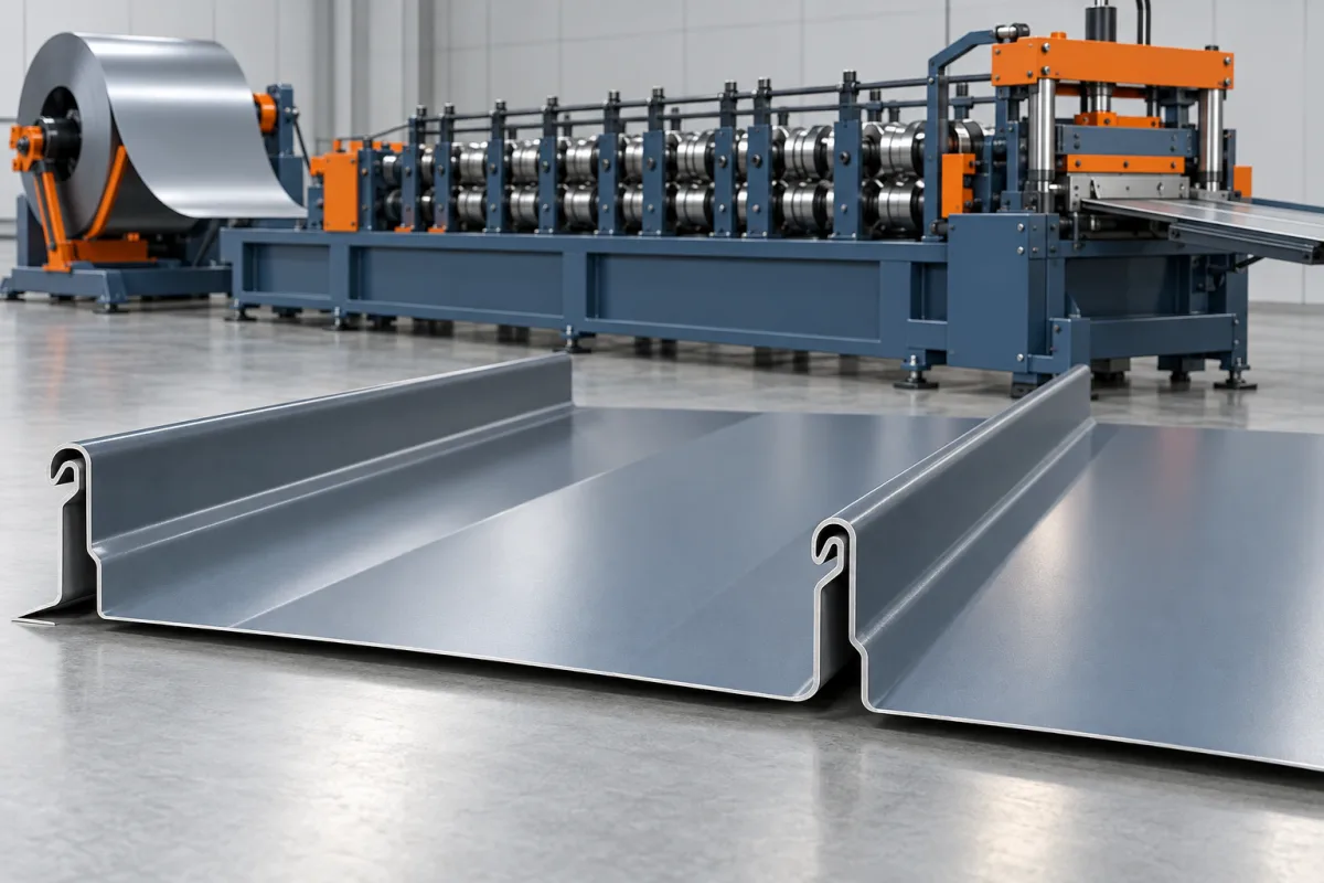
A clipless standing seam roll forming machine makes a roof-panel profile whose approved attachment arrangement does not use separate clips. In many such designs, a fixing flange becomes concealed by the adjoining panel. The exact joint and fastening detail must be specified; clipless does not mean that the panel has no fasteners or no attachment requirements.
The manufacturing focus is the relationship between the formed lock, fixing flange and any holes or slots. These features need to remain aligned through forming and cutting so the panel can be attached and joined using the intended installation sequence.
What does clipless mean for the product?
It identifies an attachment approach, not one universal seam shape. The product drawing should show how a panel is fixed before the next panel covers the attachment area. It should also show the completed joint and the clearances required for installation.
Do not describe a panel as clipless merely because a sample was supplied without clips. Confirm the actual system design. A profile intended for separate clips cannot be converted to another attachment method simply by omitting those components.
Which flange features control manufacture?
Define flange width, bend relationship, fastening access and any specified holes or slots. Show how these features are measured from the formed joint and finished ends. Their position should remain usable after the panel is cut and assembled.
- Identify the flange side and exposed-face direction.
- Record slot or hole dimensions and spacing.
- Show required solid margins near panel ends.
- Define the overlap that conceals the fixing area.
- Include the specified fastener reference in assembly trials.
Any movement-accommodating function must come from the approved system detail. The machine brief should reproduce that detail rather than inventing fastening rules from the presence of a slot.
How does it differ from a clipped standing seam?
A clipped system transfers the panel interface through a separate component. A clipless flange system integrates a fixing feature into the panel itself. This changes the formed edge, feature-making requirements and the way the attachment is checked.
Compare both product drawings if one line must serve the two approaches. Shared pan dimensions do not establish shared edge tools. The controller, guides, rolls and cutoff arrangement may need different configurations.
Where should punching occur?
The proposed process should identify whether fastening features are made before or after relevant forming stages. The choice depends on the profile, feature access and equipment design. What matters to acceptance is their final position and condition in the finished panel.
Ask how feature registration relates to cut length and panel ends. A repeating slot pattern must not leave an unintended feature in a required solid end zone. Trial several lengths, including the shortest normal order, to demonstrate the actual relationship.
How is the lock formed and protected?
Progressive rolls develop the pan, fixing flange and complementary seam edges. The sequence must preserve the geometry needed for engagement while presenting the flange features correctly. Material changes can affect the resulting return, so trials should use the intended grade and coating.
Cutoff and handling must protect the lock and flange. Inspect end distortion and any bending introduced by stacking. A panel should remain attachable and engage correctly after normal transfer, not only immediately after the final forming rolls.
What should material and appearance trials include?
Specify grade or alloy, thickness, coating and film. Check holes or slots for acceptable edge condition and inspect coating around formed returns. Assess visible pans separately under agreed support and lighting conditions.
Use the intended fasteners and assembly references in the trial. Record access problems or unexpected interference rather than substituting a different fixing to make the demonstration work. The result should represent the product that will actually be supplied.
Can different panel widths share the same flange?
They may share an attachment concept, but each approved width must remain within the proposed tooling and feature-making range. Ask which adjustments affect pan width and which affect slot position or edge geometry. Keep these functions clear in the product matrix.
A width-change trial should end with an attached and engaged sample. Measuring only overall width can miss a feature that shifted relative to the joint. Include guide settings, programs and cutoff support in the changeover review.
What does a complete acceptance trial prove?
- Confirm seam, flange and feature dimensions.
- Check feature spacing and end margins across several lengths.
- Inspect cutoff condition and coating.
- Attach and join representative panels using the specified method.
- Verify cover and concealment of the fixing area.
- Repeat after required changes and normal handling.
- Record accepted output and any unresolved interface issues.
The test should reflect the actual manufacturing scope. Roof-system performance and installation requirements remain defined by the approved assembly, not by the clipless label alone.
Frequently asked questions
Does clipless mean no screws are needed?
No. It means separate clips are not used in the specified attachment arrangement. The actual fastening method must be shown in the product and installation details.
Are slotted flanges always included?
No. The selected design determines the features. If slots are required, their dimensions, spacing and production equipment should be explicitly included in the line scope.
Can a clipped profile be made clipless?
Not by simply omitting the clips. It requires an approved alternative attachment design and a review of the complete formed edge, fastening access and manufacturing tools.
Why test multiple cut lengths?
Feature registration can interact with panel ends. Testing several lengths checks that holes or slots remain in acceptable positions and that required end margins are preserved.
What should the quotation request contain?
Provide the joint and flange drawing, fastener references, feature schedule, material matrix and panel sizes. State any clipped profile also required so its separate tooling scope can be assessed.
Make the attachment part of the forming brief
A useful clipless-panel proposal connects the hidden fixing flange to the seam and cut-length program. That produces a clear acceptance target and avoids treating attachment as an unspecified detail after the machine is selected.

Continue your research
- Standing Seam Roll Forming Machines
- Standing Seam Roll Forming Machine
- Snap Lock Standing Seam Machine
- 25mm Snap Lock Standing Seam Machine
- 38mm Snap Lock Standing Seam Machine
- 1 Inch Mechanical Lock Standing Seam Machine
- How Standing seam roll forming machine Works
- How To Choose a Standing seam roll forming machine
- Standing seam roll forming machine Price: What Affects the Cost?
Configuration & specification inputs
Match the configuration to your section drawing, material and production requirements.
| Parameter | Requirement / confirmation needed |
|---|---|
| Profile geometry | Approved clipless joint with integrated fixing flange or other explicitly defined attachment detail. |
| Material | Specified coated metal paired with the intended fastening and engagement system. |
| Thickness & grade | Material-thickness combinations reviewed at the lock, flange and feature edges. |
| Process route | Guided strip, registered holes or slots, seam and flange forming, cutting and protected takeoff. |
| Cutting | Lengths coordinated with fixing-feature spacing and required solid end margins. |
| Output | Accepted attachable panels with feature registration, engagement and changeover checks included. |
| Electrical supply | Utilities for feature-making, forming, cutting and the selected handling package. |
| Acceptance | Flange and seam geometry, slots or holes, fastening access, joined cover and concealed-fixing fit. |