
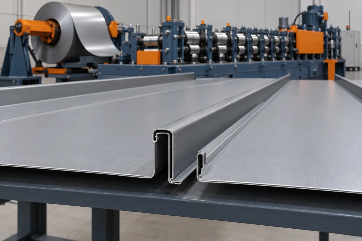
A snap lock standing seam machine forms roof-panel edges designed to engage through a specified snap-together assembly method. The key output is a matched pair of edge geometries connected by the panel pan. Their relationship to the attachment components determines whether panels assemble consistently, retain the intended cover width and preserve the required finished appearance.
This equipment is best specified around an actual snap-lock profile, not the assumption that every snap-together roof uses the same hook, clip or installation detail. Material, joint geometry and production handling need to be reviewed together because a small change in a functional return can affect the way adjoining panels engage.
What does snap-lock mean in this production context?
It describes a designed engagement between adjacent panel edges. The forming machine creates those edges, while assembly follows the chosen roof system's installation procedure. The term does not define one universal section and does not, by itself, establish whether the panel uses separate clips or a particular fixing-flange arrangement.
The equipment brief should include the joint in both its unassembled and assembled conditions. Identify which surfaces engage, where the attachment sits and how the final panel coverage is measured. This makes the forming target clearer than a drawing showing only overall width and rib height.
Which attachment and closing arrangement is intended?
Clip-attached snap-lock panels
The formed edge works with the selected clip and adjacent panel. Clip geometry, fixing access and engagement clearances must be reviewed as a system. Supply the intended components during tool development instead of leaving their selection until the machine is ready for acceptance.
Snap profiles with a covered fixing flange
Some systems use an attachment flange incorporated into the panel. Where the drawing specifies holes or slots, their geometry and production method belong in the equipment scope. Such a profile should not be treated as identical to a separate-clip design with a similar visible seam.
Profiles supporting an additional closing method
A purpose-designed product may offer an alternative closing arrangement, but that is a specific engineering feature. It does not make ordinary snap-lock panels generally interchangeable with mechanically seamed sections. Keep any proposed alternative tied to the exact profile and approved system instructions.
Which parts of the section govern engagement?
The functional opening, hook, return and contact surfaces deserve particular attention. Their complete geometry matters more than a single nominal seam dimension. Use the drawing's datums and agreed measurement method so a return is not accepted merely because its outside silhouette looks close.
The panel pan also connects the two edges and determines their relative position. Effective cover, straightness and the condition of the ends influence assembly. Inspect the complete panel after cutting rather than checking an isolated short edge sample alone.
- Define both mating edges and the completed joint.
- Identify clip contacts or the covered fixing flange.
- Record pan geometry, width and effective cover.
- Show required fixing features and their references.
- Specify the production material and finish.
- Provide the installation sequence used for assembly approval.
How does the line form a snap-lock panel?
- Coil and entry preparation: feed the specified material with consistent guidance and the correct exposed-face orientation.
- Pan development: form any specified ribs or striations while maintaining the relationship between the two edge paths.
- Progressive edge forming: develop shoulders, hooks and returns through the proposed stages.
- Feature-making: produce the specified holes, slots or notches where included in the route.
- Length cutting: cut without unacceptable distortion of the functional joint edges.
- Supported discharge and trial assembly: inspect the complete panel with its mating parts after normal handling.
Ask how the proposed tooling controls the critical engagement surfaces and which checks are used during setup. The number of stations alone does not explain whether a machine produces a repeatable joint in the required material.
How should the material envelope be reviewed?
Pair each required thickness with its grade or alloy, coating and profile configuration. Material behavior can change the final shape of tight returns after the strip leaves the tools. A successful trial in one convenient material does not establish the result across an unrelated range.
Include the actual finish in assembly trials. Coating condition should be inspected at bends and engagement surfaces after the intended installation procedure. If protective film is involved, agree its condition during the test rather than letting different trial methods create conflicting conclusions.
Record the coil identity with sample measurements and assembly observations. This allows a later fit problem to be compared with the accepted setup and material. Without that record, a change in incoming stock can be mistaken for a tooling change or vice versa.
What can change without replacing the seam tools?
Length changes, width changes and seam changes are separate questions. A proposed line may offer length control and selected width adjustments while retaining one seam design. Another joint geometry can require different rolls or other components even if the visible height remains similar.
Ask for a configuration matrix showing the intended widths, materials, pan features and joint variants. For each transition, list the tools, guides, programs and cutting components that change. Do not interpret the word adjustable as a promise that every dimension can be varied independently.
Demonstrate a meaningful transition and a return to the original accepted setting. Include assembly of the first recovered panels. This checks repeatability of the setup, not just the ability to move equipment between nominal positions.
Snap-lock versus mechanically seamed: how should a buyer decide?
Begin with the roof system required by the intended projects. Snap-together and mechanically closed seams use different defined assembly arrangements, and the equipment package should follow the chosen system. A generic claim that one category is always suitable for a particular roof condition is not enough.
Use the actual panel-system documentation for permitted applications, slope, supports, attachment and other installation requirements. These can vary between products within the same broad category. Compare the production and installation route for the specified systems rather than applying another supplier's values to a new profile.
For equipment selection, identify whether seamers, additional profiles, special ends or other auxiliary operations are needed. A snap-lock project may simplify one closing stage but still requires proper attachment components, edge quality, handling and assembly checks.
What should a joint-assembly trial include?
Use several production-intent panels and the specified attachment arrangement on an agreed support. Follow the applicable system instructions. Check that engagement occurs as intended along the tested lengths, that the resulting coverage is correct and that the edges have not been damaged during cutting or handling.
Record unusual resistance, incomplete engagement, looseness or any local modification needed to finish the assembly. Those observations are more informative than a final photograph alone. Preserve the material identity and panel measurements alongside the assembled sample.
An assembly demonstration addresses manufacturing compatibility. It is not a substitute for the roof system's required performance evidence, nor does it justify changing clips, supports or installation details without the relevant review.
How should common fit and appearance problems be investigated?
First describe the actual deviation. A panel that will not engage is different from one that engages but has an uneven seam line. Check the specified mating components, the section measurements and where the issue first appears. Use maker-approved inspection and adjustment procedures with appropriately qualified personnel.
- Engagement resistance: compare the mating returns, attachment components and material against the accepted reference.
- Inconsistent coverage: inspect both edges, panel geometry and the assembly references.
- Damaged ends: inspect the panel immediately after cutoff and after discharge to locate the source.
- Coating marks: distinguish forming contact from damage during engagement or packing.
- Pan appearance: use agreed viewing and support conditions rather than unrelated photographs.
Do not try to solve every symptom by opening or closing one return. A mismatch elsewhere in the assembly can create similar symptoms, and an uncontrolled change can move the profile away from its approved design.
What belongs in the cost and output comparison?
Quote the exact profile tools, material envelope and required variants. Add coil handling, controls, cutting components, feature-making equipment and discharge supports. State whether attachment components and other roof accessories are supplied separately. This makes it possible to compare packages that actually deliver the same product.
Measure accepted panels during a representative order with the required lengths and checks. Setup recovery, coil changes and careful handling can determine the practical output. Panels needing joint correction or replacement should not be counted as successful production simply because the strip passed through the rolls at the advertised speed.
Before acceptance, agree who inspects the joint, which components are used and how deviations are recorded. Clear responsibilities avoid a situation in which the former, clip supplier and installation team each assume another party has confirmed compatibility.
Frequently asked questions
Does snap-lock mean no attachment components are needed?
No. The panels still attach through the arrangement specified for that roof system. Depending on the design, this may involve separate clips or an incorporated fixing flange. Specify the complete attachment rather than inferring it from the closing description.
Can any snap-lock panel be used on a low-slope roof?
Use the requirements of the exact panel system. The broad category does not provide a universal minimum slope or performance rating. Obtain the appropriate project design and product documentation before selecting the profile and equipment.
Is a clip with the same nominal height interchangeable?
Not necessarily. Engagement surfaces and clearances can differ. Use the specified clip in tooling and acceptance trials. A substitution needs the relevant system review rather than a comparison of height alone.
Can the operator modify the hook to make installation easier?
Changes to a functional return should follow the approved drawing and the responsible engineering process. Uncontrolled reshaping may alter the intended joint. Investigate material, mating components and the actual deviation before considering a controlled correction.
Can one line make both snap-lock and mechanical-seam panels?
A suitably configured machine may use distinct tool sets for the required profiles, while particular engineered profiles may support alternative closing methods. Neither ability should be assumed. Ask for the exact tooling list and demonstrate the specified configurations.
What should be supplied for an equipment enquiry?
Provide the complete profile and joint drawings, attachment samples, material combinations, lengths and expected order pattern. Include required pan features and end operations. These inputs allow configuration and acceptance to be based on the actual snap-lock product.
Make joint compatibility the center of the specification
The useful result is a panel that forms, cuts, handles and assembles consistently within the selected roof system. Specify the mating geometry and components first, then evaluate tooling, changeover and accepted output around them. This gives the snap-lock line a clear production target rather than an ambiguous promise to make any standing seam.

Continue your research
- Standing Seam Roll Forming Machines
- Standing Seam Roll Forming Machine
- Mechanical Lock Standing Seam Machine
- 25mm Snap Lock Standing Seam Machine
- 38mm Snap Lock Standing Seam Machine
- 1 Inch Mechanical Lock Standing Seam Machine
- How Standing seam roll forming machine Works
- How To Choose a Standing seam roll forming machine
- Standing seam roll forming machine Price: What Affects the Cost?
Configuration & specification inputs
Match the configuration to your section drawing, material and production requirements.
| Parameter | Requirement / confirmation needed |
|---|---|
| Profile geometry | Complementary snap-lock edges, functional openings and returns, pan geometry and assembled effective cover. |
| Material | Specified coil grade or alloy and coating, with production-intent attachment components for trials. |
| Thickness & grade | Material combinations assessed against the required formed return and assembled joint. |
| Process route | Controlled entry, pan and edge forming, specified fixing features, supported cutting, discharge and assembly checks. |
| Cutting | Agreed lengths and functional-edge quality after cutoff and normal handling. |
| Output | Accepted panels with required engagement checks, changeovers and handling included in the stated trial. |
| Electrical supply | Defined site electrical supply and auxiliary requirements for the proposed package. |
| Acceptance | Mating geometry, correct attachments, joint engagement, cover, finish and first-good-panel recovery. |