
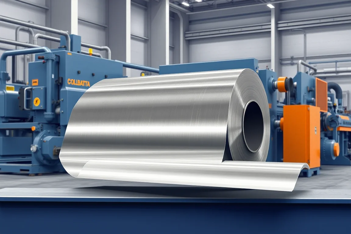
A steel coil slitting line turns a wide master coil into a set of narrower coils by running the strip through rotary knives and rewinding the resulting strips under tension. The machine is defined less by a headline width or thickness number than by the coil it can accept, the strip pattern it can hold, the edges it produces and the finished coils it can hand off. This article explains the exact finished profile, the interfaces between stations, the production route, tooling choices, changeover logic, inspection and what accepted output means in practice.
What the finished slitting line output actually is
The output of a slitting line is not a sheet and not a blank. It is a set of narrower coils, each rewound on a mandrel or sleeve, with a defined strip width, edge condition, coil inside diameter, coil outside diameter, coil mass and winding tightness. The dividing operation produces two kinds of strip at once: the ordered strips and the edge trim, plus any scrap strip created by pattern layout. A usable output profile therefore includes the ordered width pattern, the number of strips across the master coil, the width and disposition of trim, and how each finished coil is identified and removed from the recoiler.
Edge quality is part of that profile, not a separate concern. Slitting shears the strip between opposed circular knives, so the cut edge carries a characteristic combination of shear zone, fracture zone and burr. The burr height and edge condition must be defined in the acceptance conversation, because they affect downstream forming, coating adhesion and handling safety. Rewinding quality also belongs to the output definition: a coil that is wound with uneven tension, telescoped edges or loose wraps is not accepted output even if the strip width measures correctly.
Coil and strip interfaces that shape the line layout
The incoming coil sets the mechanical envelope. Coil width, base-metal thickness, grade and strength determine the forces the knives, arbors and recoiler must carry. Coil mass, inside diameter and outside diameter determine the coil car, mandrel, payoff and handling equipment. Surface condition determines whether contact rolls, hold-downs and guide surfaces need protective facings or whether standard steel contact is acceptable. All of this is buyer-defined input, and the operating range requires supplier verification rather than assumption from a generic description.
The outgoing interface is equally concrete. Each finished coil has its own inside diameter, outside diameter, mass and eye orientation. The line must be able to strip the finished coils off the recoiler, weigh or identify them and move them to the next operation without damaging the edges. If the finished coils are heavy or numerous, the removal method and handling equipment can dominate the achievable output, so it belongs in the layout rather than in an accessory list.
The production route from payoff to finished coil
A conventional route runs through safe coil loading, payoff, strip preparation, slitting, tension control, recoiling and handling. Coil loading uses a coil car or crane-served mandrel to place the master coil on the uncoiler. Payoff releases the strip under controlled tension and feeds it into the line. Strip preparation may include peeler and hold-down devices, a straightener or leveler to remove coil set, and a shear or crop station to square the leading end before threading.
At the slitter, the strip passes through paired circular knives mounted on upper and lower arbors, with spacers setting the strip widths. After the slitter, a scrap winder or chopper handles edge trim and any center scrap. The slit strips then pass through a tension device, which may be a drag pad, a bridle or a tension stand, before entering the recoiler. The recoiler winds the strips into finished coils, often with a separator shaft or stripper plate to keep adjacent strips apart and to push coils off the mandrel. Overlap and separator discs prevent interleaving during winding.
Slitter tooling and pattern alternatives
Tooling choice follows the width pattern and edge requirement. A fixed-knife setup uses spacers and knives arranged for one width pattern; it is straightforward and rigid but requires physical rearrange for a different pattern. A quick-change or cartridge-style slitter head lets a prepared arbor set be exchanged as a unit, moving setup work off the line. Removable spacer systems and programmable positioning reduce the manual work of setting widths, but they add their own calibration and maintenance obligations.
Knife geometry and material also matter. The knife diameter, thickness, edge angle and side clearance influence the cut quality and burr. Different strip grades and thicknesses respond differently to a given clearance and edge angle, so a tooling set that performs well on one material is not automatically correct for another. This is why the tooling scope should be tied to the defined material range rather than treated as a single universal setup.
Leveling, tension and recoiling: separate functions inside the line
Slitting is not the same operation as leveling or cut-to-length. A leveler changes flatness by bending the strip through a series of rolls; it does not change width. Slitting changes width by shearing; it does not by itself correct coil set or crossbow. When a line combines a straightener or leveler with a slitter, the two functions should be evaluated separately, because the roll arrangement that suits one material and thickness may not suit another.
Tension and recoiling are also distinct from the cut. Tension controls the winding tightness and prevents the strips from wandering as they are rewound. The recoiler holds and rotates the finished coils, and its mandrel, gripper and stripper design determine how cleanly the coil can be removed. A line with good slitting but weak tension control can still produce unacceptable finished coils.
Cut-to-length versus slitting: how to distinguish the two lines
A cut-to-length line takes a coil and produces flat sheets or blanks by measuring length and cutting across the strip. A slitting line takes a coil and produces narrower coils by cutting along the strip. They answer different questions. If the next operation needs a narrower coil to feed a roll former, a tube mill or a stamping press, slitting is appropriate. If the next operation needs discrete flat pieces, cut-to-length is appropriate. Some facilities run both, but the equipment, tooling and acceptance checks differ, and a single machine is not normally both.
Decoiler and leveling equipment can appear in either route. A hydraulic decoiler provides controlled payoff and mandrel expansion; a leveler improves flatness before downstream processing. These are supporting functions, not substitutes for the slitting or cutting operation itself.
Changeover and setup realities
Changeover is often where the practical difference between lines appears. Changing a strip-width pattern may require removing the slitter head, replacing spacers and knives, re-threading the strip, setting tension and adjusting the recoiler. Quick-change heads and prepared arbors reduce the time the line is stopped, but they require storage, handling and pre-setting discipline. The written changeover procedure should list the steps, the checks at each step and who performs them.
Tooling preparation can happen away from the line, which decouples it from production time but adds a parallel workflow. Setup scrap arises from threading, from the first length used to establish tension and from any trial cuts. The timing of finished-coil removal and scrap handling should be measured together with the cut, because a line that slits quickly but waits on coil removal does not deliver the expected output. Ask what must change for another material thickness or strip-width pattern, including tooling preparation and setup checks, and include scrap handling and finished-coil removal in the timing.
Inspection and accepted output
Acceptance for a slitting line centers on strip width, edge burr and recoiling quality. Width is checked against the ordered pattern and tolerance. Edge burr is examined for height and consistency along the coil. Recoiling quality covers winding tightness, edge alignment, telescoping and surface condition. The agreed gauges and sampling method should be written before the run, and the inspection should be performed on the actual material and pattern rather than on an easier demonstration substitute.
It is also important to distinguish incoming coil defects from process-induced damage. Edge cracks, slivers, rust, laminations and camber that arrive with the master coil should be identified at goods-in, photographed or logged, and separated from defects created by slitting, tension or rewinding. Without that separation, responsibility for rejected output becomes a dispute rather than a measurement. First-off pieces and a representative steady-production sample should both be inspected, because a single good start does not prove stable output.
Handling, safety and auxiliary scope
Coil handling equipment is not optional overhead. Coil cars, mandrels, coil lifters, scrap winders, choppers, separators and finished-coil removal devices all affect whether the line can sustain production. Safety provisions such as guards, interlocked access doors, emergency stops and safe threading procedures belong in the layout from the start. Omitted handling or safety equipment can make an otherwise attractive scope incomplete, so the written equipment list should be compared with the full sequence of operations needed to turn a master coil into a removable finished coil.
Practical checklist for specifying and accepting a line
- State the incoming coil envelope: width, thickness, grade, strength, mass, inside diameter, outside diameter and surface condition.
- State the finished profile: ordered strip widths, trim disposition, edge and burr expectation, coil inside and outside diameters and coil mass.
- Confirm the production route and which stations are included: loading, payoff, leveling, slitting, tension, recoiling and handling.
- Decide the tooling approach: fixed knives, quick-change heads, removable spacers or programmable positioning, and how tooling is prepared and stored.
- Define changeover steps, setup scrap, threading time, scrap handling and finished-coil removal, and include them in output expectations.
- Write the inspection method for width, edge burr, winding tightness and edge alignment, with gauges and sampling.
- Separate incoming coil defects from process-induced damage, and record how each is handled.
- Confirm electrical supply, voltage, frequency and phase, and require a confirmed equipment schedule for installed power.
- Run the agreed material and profile, and inspect both first-off and steady-production samples.
- Compare accepted output for the actual job mix, not for a single convenient demonstration.
FAQ
What is the difference between a slitting line and a cut-to-length line?
A slitting line cuts along the strip to produce narrower coils. A cut-to-length line cuts across the strip to produce flat sheets or blanks of controlled length. The downstream operation determines which is needed: a roll former or tube mill usually needs a narrow coil, while a press or panel process may need discrete pieces.
How is the strip-width pattern set on a slitting line?
The pattern is set by the arrangement of circular knives and spacers on the slitter arbors. Each ordered strip width corresponds to a spacing between knife pairs. Changing the pattern means changing that arrangement, which may be done on the line or on a separate prepared head, depending on the tooling approach.
What causes burr on a slit edge, and can it be controlled?
Burr comes from the shearing action of the knives and is influenced by knife edge condition, side clearance, strip thickness, material strength and tension. It can be managed by matching tooling and setup to the material and by defining an acceptable burr level in the acceptance criteria rather than assuming any burr is acceptable.
Why does recoiling quality matter as much as strip width?
A coil that is wound loosely, with telescoped edges or interleaved wraps, can be difficult to uncoil and can damage the strip surface or edges downstream. Recoiling quality depends on tension control, separator and overlap devices, and the recoiler mandrel and stripper design, so it is a line-level result rather than a slitter-only result.
Should leveling be included in the same line as slitting?
It can be, but the two operations solve different problems. Leveling addresses flatness such as coil set, crossbow or edge wave, while slitting addresses width. Combining them can be efficient when the material range is compatible, but the leveler and slitter should still be specified and accepted as separate functions.
How should changeover time be assessed when comparing options?
Assess it as the total time the line is stopped for a pattern change, including tooling removal, replacement, re-threading, tension setup, trial cuts and first-piece verification. Also account for the parallel work of preparing tooling away from the line and for setup scrap, because those affect usable output even when they do not occur on the machine.

Continue your research
- Coil Processing & Auxiliary Equipment
- Cut To Length Line
- Hydraulic Decoiler
- Narrow Strip Steel Coil Slitting Line
- High Speed Steel Coil Slitting Line
- Heavy Gauge Steel Coil Slitting Line
- How Coil processing line Works
- How To Choose a Coil processing line
- Coil processing line Price: What Affects the Cost?
Configuration & specification inputs
Match the configuration to your section drawing, material and production requirements.
| Parameter | Requirement / confirmation needed |
|---|---|
| Profile geometry | A slitting line divides a wide coil into narrower coils. Specify strip widths, edge quality, material range and finished-coil handling; a cut-to-length line performs a different task. |
| Material | Defined coil grades and surface conditions within a verified capacity envelope |
| Thickness & grade | Buyer to specify base-metal thickness and grade; operating range requires supplier verification. |
| Process route | Safe coil loading → payoff → leveling or slitting → length control/recoiling → handling |
| Cutting | Confirm profile-supported cutoff, cut lengths, end quality and any secondary operations. |
| Output | Define accepted output per shift with the actual profile and material. |
| Electrical supply | Buyer to state voltage / frequency / phase. Installed power requires a confirmed equipment schedule. |
| Acceptance | Ask what must change for another material thickness or strip-width pattern, including tooling preparation and setup checks. Include scrap handling and finished-coil removal in the timing. Compare accepted output for the actual job mix. |