
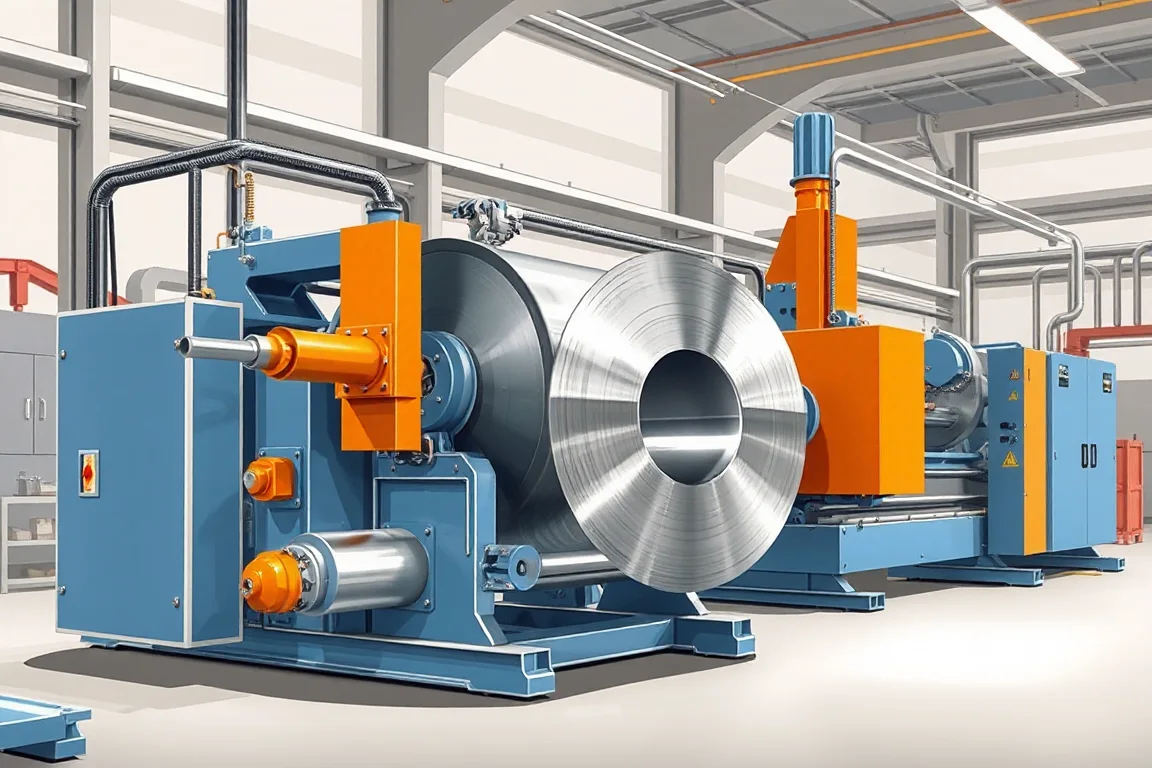
What the line actually does and why integration matters
The core job of a decoiler straightener feeder line is to transform a stored coil into a stream of flat strip delivered at the right length and timing for the next operation. A decoiler supports the coil and controls payoff tension or speed. A straightener applies controlled bending to the strip to remove curvature inherited from coiling. A feeder grips and advances the strip by a set pitch, then releases for the next stroke or cut. Because these functions interact, the line must be selected as a system. A straightener that is adequate in isolation can still cause feed errors if its output does not match the feeder's grip and timing, or if the loop between modules is not managed.
Integration also determines the real operating cycle. Coil loading, threading, loop formation, feed acceleration, and end-of-coil handling all consume time. A maximum strip speed figure, even if verified for a specific configuration, does not describe how many acceptable parts the line can produce per shift. Buyers should define the material envelope, feed pitch, control interface, and available loop space before comparing layouts.
Component interfaces: decoiler, straightener, feeder, and downstream process
The decoiler interfaces mechanically with the coil and electrically or hydraulically with the line controller. Its mandrel or support must match the coil inside diameter, and its payoff mode must be compatible with the loop or tension arrangement. If the line uses a free loop, the decoiler runs on a dancer or loop control; if it uses tension, the decoiler must provide consistent back tension without marking the strip surface.
The straightener interfaces with the strip through its roll arrangement. The number and diameter of rolls, the adjustment method, and the roll surface condition all affect how much coil set can be removed. The straightener also interfaces with the feeder: the strip leaving the straightener must be presented to the feeder at a consistent height and angle, or the feeder will fight the strip rather than advance it.
The feeder interfaces with the downstream press or process through its control signal. A feeder may be mechanically linked, electrically synchronized, or controlled by a separate motion controller. The feed pitch, acceleration, and release timing must match the downstream cycle. If the line feeds a press, the feeder must not advance while the press is closed; if it feeds a cut-to-length shear, the feeder must stop accurately for the cut. These are control-interface decisions, not just mechanical ones.
Material and coil inputs that shape the configuration
The incoming coil defines the practical limits of the line. Coil width, thickness, mass, inside diameter, and outside diameter all influence the decoiler's support and payoff design. Thickness and width must be paired with grade and strength, because a strip that is easy to level in one grade may resist leveling in another. Surface-sensitive material may require special contact surfaces, protective sleeves, or handling precautions to avoid scratches and marks.
The required strip or blank defines the output. If the line feeds a press, the feed pitch and strip width define the blank or part. If the line includes a shear, the cut length and squareness define the output. If the line includes slitting, the strip width and edge quality define the output. These are different acceptance criteria and should be stated explicitly rather than assumed.
Production routes: leveling, slitting, and cut-to-length are not interchangeable
A decoiler straightener feeder line can sit in front of several different production routes. In a leveling-and-feeding route, the line prepares strip flatness and feeds a press or roll former. The acceptance focus is feed length, flatness, and surface condition. In a slitting route, the line may include a slitter that cuts the coil into narrower strips, followed by recoiling. The acceptance focus shifts to width, edge burr, and recoil quality. In a cut-to-length route, the line includes a shear or cutoff and may stack or stack-and-count sheets. The acceptance focus becomes length, squareness, and flatness.
These routes require different modules and different control strategies. A slitting line needs a slitter arbor, knife setup, and recoiler or tension system. A cut-to-length line needs a shear, length gauge, and stacking or handling equipment. A leveling-and-feeding line needs a straightener and feeder matched to the downstream process. Mixing these routes in one quotation without clarifying the scope can lead to missing equipment and unrealistic performance expectations.
Assembly boundaries and scope definition
Assembly boundaries are the physical and contractual lines between what the equipment supplier provides and what the buyer or another party provides. Mechanically, the boundary may fall at the decoiler base, the straightener entry, the feeder exit, or the interface with the press. Electrically, the boundary may fall at the line control panel, the press control panel, or a junction box. Hydraulically or pneumatically, the boundary may fall at a manifold or a quick-disconnect.
These boundaries matter because they determine who supplies the coil car, the threading table, the loop pit, the scrap conveyor, the recoiler, and the safety guarding. Material handling equipment can dominate the real production cycle, and omitted handling equipment can make an apparently low quote incomplete. A written scope should identify each module, each utility connection, and each interface signal.
Application-specific inspection and acceptance checks
Inspection should be tied to the application. For a leveling-and-feeding application, inspect first-off pieces and a representative steady-production sample for feed length, flatness, and surface condition. For a slitting application, inspect strip width, edge burr, and recoil quality. For a cut-to-length application, inspect length, squareness, and flatness. In all cases, define how incoming coil defects are distinguished from process-induced damage. A scratch that existed on the coil before processing is not a line defect, but it may still affect the finished part.
Acceptance should also cover the operating cycle. Record changeover steps, setup scrap, threading time, and unloading time. Compare the written equipment scope with all secondary operations needed for a finished part. Run the agreed material and profile, not an easier demonstration substitute. These checks make the difference between a line that performs in a trial and a line that performs in production.
Comparing alternatives: standalone modules versus integrated line
One alternative to an integrated decoiler straightener feeder line is a set of standalone modules: a separate decoiler, a separate straightener, and a separate feeder, each with its own controls. This can offer flexibility if the modules are used in different combinations, but it also multiplies the number of interfaces and can increase floor space and commissioning effort. Another alternative is a compact line that combines decoiler, straightener, and feeder on a common base. This can simplify alignment and reduce loop space, but it may limit the range of coil sizes or strip widths that can be handled.
A third alternative is a dedicated slitting line or cut-to-length line that includes a decoiler and straightener but serves a narrower purpose. These lines may be more efficient for their specific output, but they are not interchangeable with a feeder line. The right choice depends on the required output, the material envelope, and the downstream process. If the downstream process changes frequently, an integrated line with a clear control interface may be easier to adapt. If the output is fixed and high-volume, a dedicated line may reduce handling and setup.
FAQ: decoiler straightener feeder line decisions
What is the difference between a straightener and a leveler?
In common usage, a straightener removes coil set and gross curvature using a series of rolls. A leveler typically uses more rolls and finer adjustments to improve flatness. The terms are sometimes used interchangeably, but the required flatness and material grade should drive the roll arrangement and adjustment method, not the label.
Can a decoiler straightener feeder line handle both slitting and cut-to-length?
Some lines are configured for one route, and some are designed for changeover between routes. Slitting requires a slitter and recoiler; cut-to-length requires a shear and length control. Combining them in one line is possible but increases complexity and should be justified by production volume and changeover time.
How do I define the feed pitch for a press feed line?
Feed pitch is determined by the part or blank length and the downstream process. It must be stated with the material, thickness, and required feed accuracy. The feeder's grip and release timing must match the press cycle. This is a control-interface requirement, not a standalone feeder rating.
What causes strip marking in a decoiler straightener feeder line?
Strip marking can come from decoiler mandrel contact, straightener rolls, feeder grips, or handling equipment. Surface-sensitive material may need softer contact surfaces, protective films, or reduced tension. The cause should be identified by inspecting the strip at each module, not assumed.
Which inspections are most important for a slitting line?
For slitting, width, edge burr, and recoil quality are the primary acceptance checks. These should be measured on first-off and steady-production samples. Incoming coil edge condition should be recorded so that pre-existing defects are not attributed to the slitting process.
How should electrical supply and installed power be addressed?
The buyer should state voltage, frequency, and phase. Installed power requires a confirmed equipment schedule, not an estimate. The equipment supplier should provide a schedule that lists each motor and heater, and the buyer should verify that the available supply can support it.
Practical checklist before approving a line
- Define the coil width, thickness, mass, inside diameter, and outside diameter.
- State the material grade and surface condition, and verify the capacity envelope.
- Clarify the production route: leveling and feeding, slitting, or cut-to-length.
- Specify the feed pitch, cut length, or strip width required by the downstream process.
- Identify the control interface between the feeder and the press or shear.
- Confirm the available loop space and the method of loop or tension control.
- List all material handling equipment: coil car, threading table, scrap conveyor, recoiler, stacker.
- Agree on inspection criteria for the specific application, including first-off and steady-production samples.
- Record changeover steps, setup scrap, and unload time as part of the operating cycle.
- Verify that the installed power schedule matches the available electrical supply.
These steps help distinguish a complete, application-specific line from a collection of modules. The goal is not to maximize a single specification but to match the line to the coil, the downstream process, and the production reality.

Continue your research
- Coil Processing & Auxiliary Equipment
- Steel Coil Slitting Line
- Cut To Length Line
- Narrow Strip Steel Coil Slitting Line
- High Speed Steel Coil Slitting Line
- Heavy Gauge Steel Coil Slitting Line
- How Coil processing line Works
- How To Choose a Coil processing line
- Coil processing line Price: What Affects the Cost?
Configuration & specification inputs
Match the configuration to your section drawing, material and production requirements.
| Parameter | Requirement / confirmation needed |
|---|---|
| Profile geometry | A decoiler-straightener-feeder system must match the downstream press or process. Define feed pitch, control interface, material envelope and available loop space before comparing layouts. |
| Material | Defined coil grades and surface conditions within a verified capacity envelope |
| Thickness & grade | Buyer to specify base-metal thickness and grade; operating range requires supplier verification. |
| Process route | Safe coil loading → payoff → leveling or slitting → length control/recoiling → handling |
| Cutting | Confirm profile-supported cutoff, cut lengths, end quality and any secondary operations. |
| Output | Define accepted output per shift with the actual profile and material. |
| Electrical supply | Buyer to state voltage / frequency / phase. Installed power requires a confirmed equipment schedule. |
| Acceptance | Review coil loading, threading, loop or compact arrangements and the required feed pattern. Trial the actual material with the downstream process. Safe access, guarding and stored-energy isolation belong in the equipment integration review. |