
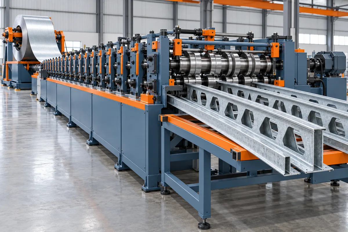
A light gauge steel floor joist machine produces the specified cold-formed members used in a designed floor system. The term can refer to solid-web joists or members used in an assembled joist arrangement, so the finished product must be defined before machinery is compared. A general framing line does not automatically include every floor-member profile or feature.
Floor production places particular importance on bearing and connection details, service openings, member identity and the relationship between adjacent components. The equipment should turn approved design data into parts that assemble without unplanned cutting or hole modification.
Which floor-member system is being manufactured?
Identify the section and assembly type. A deep C joist, an open-web assembly and a special built-up member can need different forming and fabrication routes. Provide the complete component list rather than asking one machine to make an undefined floor joist.
Show web, flanges, lips and local end details on controlled drawings. Include rim, track, blocking, stiffener or connector references where they affect fit. The production scope should distinguish primary members from their accessories.
How should bearing and end connections be described?
Define the approved end geometry, attachment features and mating components. The machine needs the dimensions and locations necessary to manufacture those details, while structural design determines their suitability.
Use representative connections in the trial. A joist can have the correct cross-section and length while an incorrect end feature prevents assembly. Avoid approving only a long blank member when production normally includes connection preparation.
What is required for service openings?
Specify opening shape, size and permitted location from the approved design. Different openings can require different tools, including any localized formed edge that the design calls for. Do not treat all holes as interchangeable punching operations.
- Identify the member datum and end distances.
- Separate large service openings from connection holes.
- Show zones where openings are not permitted.
- Define orientation and any formed opening detail.
- Record the drawing revision controlling the pattern.
The machine's punching capacity does not authorize arbitrary openings. Manufacturing programs should follow the designed feature schedule and retain its traceability.
How should project information reach the line?
Define the data path from approved joist schedule to lengths, features and part identifiers. Verify units, section selection, handedness and revisions. The operator should be able to connect each finished member to its intended assembly location.
Test a representative floor bay or connection group before large-scale production. This checks whether design data, machine programming and identification work together. A successful software import is only one part of that verification.
What does the manufacturing route include?
Coil preparation feeds the specified punching and forming operations. Progressive tools create the joist section, followed by cutting and marking. Depending on the floor system, additional assembly, fastening or accessory production may remain outside the roll-forming line.
Identify these downstream operations explicitly. A complete member former is not necessarily a complete floor-system factory. The equipment schedule should show which process supplies every component needed for the representative assembly.
How should materials and profile variants be reviewed?
Pair grade, thickness and coating with each joist section. Deeper webs, different flanges or localized features can create distinct forming cases. Use a matrix rather than combining separate dimensional and material maxima.
Trial the actual material through both ordinary section forming and the required openings. Inspect feature edges, bends, straightness and twist. Retain material identification with the member and assembly results.
What should be checked before floor assembly?
Measure section geometry, length, end preparation and service-opening registration. Verify member identity and orientation. Inspect local deformation near punched features and cut ends separately from overall straightness.
Then assemble the representative connections and accessory interfaces. Record any extra trimming, drilling or forcing needed. Those observations show whether the production route delivers assembly-ready components or merely approximate starting pieces. Include the intended rim or bearing reference in this check, because a loose joist sample cannot establish the final end relationship by itself.
How should output be compared?
- Use a representative joist schedule with real feature density.
- Include required accessories or clearly exclude their manufacture.
- Measure accepted identified members after handling.
- Record feature-tool and profile changes.
- Include sorting and assembly preparation where required.
- Track rejected features and startup material.
A strip-speed figure can be misleading when large openings, short pieces or multiple feature patterns dominate the cycle. Compare the accepted components needed for a floor assembly under the same stated scope.
Frequently asked questions
Can a wall-framing machine make floor joists?
Only if it covers the actual joist section, material and feature operations. A shared cold-formed-steel process does not establish the required depth, openings or assembly capability.
Can service holes be added wherever convenient?
No. Their locations and details must follow the approved member design. Machine convenience should not override structural feature requirements.
Does the machine make complete open-web joists?
Not unless the proposal includes all required member production and assembly operations. Define the finished joist system and identify what remains downstream.
Why include rim or blocking references?
They reveal interface issues that loose-joist measurements can miss. The trial should demonstrate the connections and assembly relationships that normal production must satisfy.
What is the best trial project?
A small representative floor assembly containing typical bearings, service openings and member lengths. It tests the complete data-to-component route without relying on an idealized blank sample.
Evaluate the line through a real floor assembly
A useful joist-machine specification connects section forming to openings, end connections and project identity. That produces a meaningful acceptance target: components that fit the designed floor system without unplanned workshop correction.

Continue your research
- Stud & Track Roll Forming Machines
- Drywall Stud Roll Forming Machine
- Drywall Track Roll Forming Machine
- C89 Light Gauge Steel Framing Machine
- C140 Light Gauge Steel Framing Machine
- Top Hat Light Steel Framing Machine
- How Stud and track roll forming machine Works
- How To Choose a Stud and track roll forming machine
- Stud and track roll forming machine Price: What Affects the Cost?
Configuration & specification inputs
Match the configuration to your section drawing, material and production requirements.
| Parameter | Requirement / confirmation needed |
|---|---|
| Profile geometry | Approved floor-member section and assembly type with defined bearings, ends and accessory interfaces. |
| Material | Design-specified steel grade and coating assigned to each joist component. |
| Thickness & grade | Per-section material-thickness matrix including the required service-opening process. |
| Process route | Controlled joist schedule, feature making, forming, cutting, marking and defined downstream assembly. |
| Cutting | Project lengths and end preparation coordinated with bearing and connection details. |
| Output | Accepted identified joist components or explicitly scoped assemblies for the representative floor schedule. |
| Electrical supply | Utilities for feature-rich forming, cutoff, marking and any included accessory operations. |
| Acceptance | Section, service openings, bearing features, orientation, actual connection fit and recorded correction work. |