
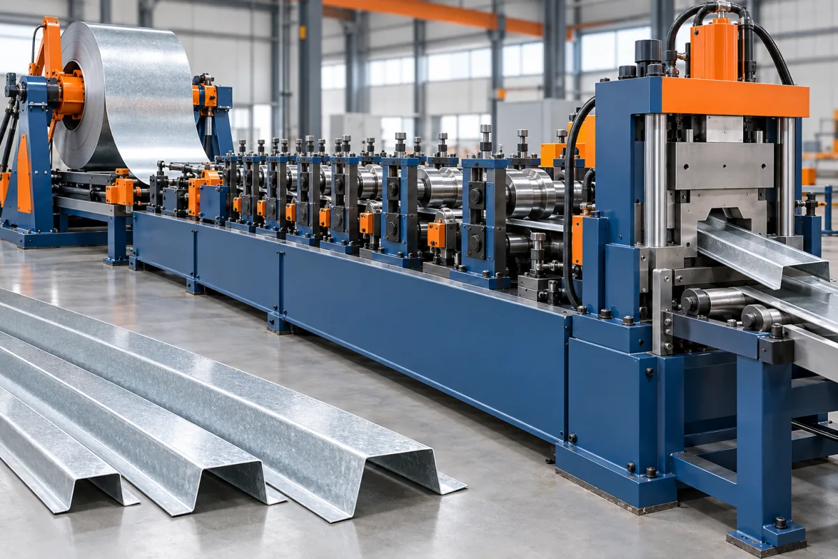
A top hat light steel framing machine produces a raised-crown section with outward feet used in the specified light-steel support or framing arrangement. The profile can resemble a small omega section, but its exact dimensions, material and connections define the product. The machine should be chosen for that drawing rather than the general hat-shaped appearance.
Top hat members differ from C studs because the support and fixing surfaces are arranged around a crown and two feet. This can change feature access, assembly references and stacking behavior. A useful production brief explains those interfaces before discussing speed or automation.
Which top-hat dimensions need to be controlled?
Show crown width, overall depth, sidewall angles, foot widths and any returns or beads. Identify whether the section is symmetric and which surfaces must align in the installed assembly. Include bend radii and the material-thickness convention.
Keep developed strip width separate from overall projected width. The sidewalls and returns consume material that is not visible in the outside footprint. The input-coil specification should be confirmed for the approved tool design.
How does the member fit the framing system?
Provide the connection drawing showing which surfaces contact the supporting structure and which support the attached component. Include clips, fasteners or brackets where they determine fit. The intended load path and spacing belong to the system design.
Do not transfer an interface from a ceiling furring channel simply because the shapes look similar. A top-hat framing member may have different material, depth or connection requirements and needs its own controlled reference.
Which features and markings are required?
Specify holes or slots in the crown or feet, any local notches and the member identification. Define feature locations from finished-section datums and cut ends. The drawing should make clear which side faces the assembly reference.
- Hole pattern and permitted unmodified zones.
- Foot or crown location of each feature.
- Special end preparation.
- Length and orientation identifiers.
- Any downstream operations not completed by the line.
Use the actual assembly features in the trial. A blank hat section may form well while the finished punched product presents different handling or fit questions.
How is the crown-and-foot geometry formed?
Guided strip moves through progressive stages that develop the raised crown and outward feet. The sequence must maintain tool access and preserve the required contact relationships. Feature making and any surface detailing need a defined place in that route.
The cutoff should support the section so the crown and feet remain usable at the ends. Review the transfer immediately after cutting because light sections can be distorted by unsuitable support or package restraint.
How should material combinations be reviewed?
Pair grade, base-metal thickness and coating with the target section. The same geometry in a different material is a separate forming case. Ask for an approved matrix rather than a general claim that the line handles light steel.
Inspect bend condition, feature edges and any specified surface texture. Retain coil identity and representative samples. Where the product family contains several depths or foot widths, include demanding combinations in the acceptance plan.
Can one line make different hat sizes?
That depends on the tooling arrangement. Crown width, depth and foot width may not vary independently, and changes can affect feature references or input width. Request a schedule of adjustments and replacement tools for every intended variant.
Time changeover through an accepted member and a mating-interface check. A quick tool movement is not the same as recovering the correct relationship between the crown, feet and connection features.
Which geometry checks matter most?
Measure crown height and width, foot position, angles and any returns. Check straightness and twist on agreed supports. Inspect whether the designated contact surfaces sit in the required relationship without forcing the part into a fixture.
Compare the section near cut ends with an interior measurement. Local flare or crushing should be recorded separately. Recheck after normal stacking to ensure the accepted light section survives the handling route.
What should a representative trial prove?
- Confirm section, material and feature references.
- Produce normal and boundary variants.
- Measure crown, feet, angles and features.
- Check the intended attachment and supported-component fit.
- Inspect ends, straightness and twist.
- Verify member identification and packaging.
- Record accepted output for the actual length and feature mix.
Keep structural design approval separate from the machine trial. The equipment should make the specified member consistently; it does not determine where that member may be used simply by reproducing a hat shape.
Frequently asked questions
Is top hat the same as omega?
The names can describe similar families, but they do not establish identical sections. Compare the complete dimensions, material and connection drawing before treating tools or parts as interchangeable.
Can a C-stud machine make top hats?
Only if the corresponding tooling and feature arrangement are included. The crown-and-foot geometry is different from a C section and needs its own process review.
Should both feet always lie in one plane?
Follow the actual drawing and contact requirements. Define the inspection method so the intended relationship is checked without forcing the member into an artificial shape.
Can holes be moved for easier punching?
Only through an approved design change. Feature positions are part of the member's connection specification, not a convenience setting to alter without review.
What should the enquiry include?
Send the section and assembly drawings, material matrix, features, lengths and required variants. Add packaging and identification needs so the proposal covers usable components.
Specify the contact surfaces as carefully as the outline
A top-hat framing line should be evaluated through the crown, feet and real connection interfaces. That turns a familiar profile shape into a clear manufacturing and acceptance specification.

Continue your research
- Stud & Track Roll Forming Machines
- Drywall Stud Roll Forming Machine
- Drywall Track Roll Forming Machine
- C89 Light Gauge Steel Framing Machine
- C140 Light Gauge Steel Framing Machine
- Light Gauge Steel Floor Joist Machine
- How Stud and track roll forming machine Works
- How To Choose a Stud and track roll forming machine
- Stud and track roll forming machine Price: What Affects the Cost?
Configuration & specification inputs
Match the configuration to your section drawing, material and production requirements.
| Parameter | Requirement / confirmation needed |
|---|---|
| Profile geometry | Approved top-hat crown, sidewalls, outward feet, returns and installed orientation. |
| Material | Specified light-steel grade and coating for the intended support or framing system. |
| Thickness & grade | Material-thickness combinations reviewed with crown, depth and foot variants. |
| Process route | Guided strip, registered features, crown-and-foot forming, supported cutoff and identification. |
| Cutting | Required member lengths with undistorted contact surfaces and correctly located end features. |
| Output | Accepted top-hat components for the stated length, feature and size-change mix. |
| Electrical supply | Utilities matched to the selected forming, feature-making and handling arrangement. |
| Acceptance | Crown and foot relationships, features, straightness, twist, actual attachments and condition after stacking. |