
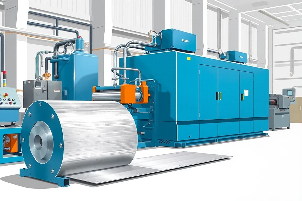
A cut-to-length line converts coiled metal into flat sheets or blanks of predetermined length. Unlike a slitting line, which produces narrower strips, a cut-to-length line delivers discrete pieces. The value of the line depends on how well it matches the incoming coil, the required flatness and the downstream handling. This article explains the exact finished profile, the interfaces between components, the production route, tooling alternatives, separate operations, changeovers, inspection and what constitutes accepted output.
What the finished profile actually is
The finished profile is a flat sheet or blank defined by length, width, squareness and flatness. Width comes from the coil width, possibly trimmed or slit beforehand. Length is set by the cut-to-length control. Squareness is the deviation of a cut edge from a true right angle to the strip edge. Flatness describes how much the sheet deviates from a plane when laid on a reference surface. The line must produce pieces that meet the drawing’s tolerances for these attributes, not merely cut coil into pieces. The profile also includes edge condition: burr height and edge quality may be specified for downstream joining or painting. For some parts, the blank may have notches, holes or contour cuts, but those are secondary operations beyond a basic cut-to-length line.
Interfaces between coil, line and downstream operations
A cut-to-length line sits between coil storage and the next manufacturing step. On the input side, the coil’s inside diameter, outside diameter, width, thickness, mass and surface condition must be compatible with the decoiler, threading equipment and leveler. On the output side, the sheet or blank must interface with conveyors, stackers, packaging or directly with a press or welding cell. The line’s control system must also communicate with upstream and downstream equipment if the whole process is automated. Ignoring these interfaces leads to bottlenecks: a fast line that cannot keep up with coil changes, or a stacker that cannot handle the blank size without manual intervention.
Production route: from coil to accepted sheet
The typical route is: safe coil loading → payoff → leveling → length control → cutting → handling. Safe coil loading uses a coil car, crane or lift to place the coil on the decoiler mandrel. Payoff unwinds the coil, often with a hydraulic or mechanical brake to maintain tension. Leveling removes coil set and improves flatness. Length control uses a measuring system, such as a servo roll or encoder, to feed the exact length before cutting. Cutting is done by shear, guillotine or other cutoff method. Handling moves the cut piece to a stacker or conveyor. Optional operations include edge trimming, slitting, punching or notching, but these are separate modules. The route should be documented as a layout showing every operation included in the quoted scope.
Payoff and coil loading: more than a decoiler
The decoiler supports the coil and allows it to rotate. A hydraulic decoiler expands its mandrel to grip the coil’s inside diameter. The payoff process must control tension so the strip does not unspool too quickly or drag. Coil loading is a significant part of the cycle; a coil car can reduce crane dependency and improve safety. Threading the strip through the line is another manual step that can be mechanized with thread tables, peelers or hold-down arms. When comparing quotes, ask how coil loading, threading and coil end handling are performed and whether these operations are included. Omitting them makes a low quote incomplete.
Leveling: matching capability to incoming material
Leveling reduces coil set, crossbow and other shape defects. The leveler’s roll arrangement, roll diameter, backup supports and adjustment method determine what it can flatten. A leveler that works for mild steel may not flatten high-strength or thick material. The number of rolls, the roll gap and the ability to adjust individually or in groups matter. For surface-sensitive material, roll surfaces and cleaning must be considered to avoid marking. Leveling capability must be matched to the incoming coil’s yield strength, thickness and initial flatness. The line’s flatness acceptance should be defined by how the sheet behaves on a flat surface, not by a vague claim of “leveled.”
Length control and cutoff: how the length is achieved
Length control can use a servo feed, a measuring roll or a combination. The feed system accelerates the strip, measures the length and stops it for cutting. Accuracy depends on the measurement method, the strip’s inertia and the response of the stopping mechanism. Cutoff is performed by a shear, often a guillotine or a flying shear for continuous operation. The cutoff tooling must be compatible with the material thickness and grade. Edge quality after cutting may require deburring or a different cutting method. The cut length range and any secondary cuts, such as notching, should be confirmed for the specific profile. The control system should allow storing multiple cut lengths and switching between orders with minimal setup.
Tooling alternatives: shear, knife and feeder choices
Different tooling answers different problems. A guillotine shear is common for cut-to-length lines; it cuts across the strip with a blade. A flying shear cuts while the strip is moving, allowing continuous production. Rotary shears cut with rotating blades and can be used for higher speeds or specific edge quality. The choice depends on material, thickness, cut length and required edge condition. For leveling, tooling alternatives include different roll materials and coatings for surface protection. Feed rolls may be polished or coated to avoid marking. The feeder design—whether it uses pinch rolls, a gripper feed or a servo roll—affects accuracy and surface contact. These choices are not interchangeable; each has trade-offs in speed, accuracy and material compatibility.
Separate operations: what is not part of the basic line
A cut-to-length line may be quoted with only the core functions. Slitting, punching, notching, edge trimming and stacking are often separate operations or modules. Slitting creates narrower strips and requires a slitting head with knives. Punching and notching require a press or dedicated station. Stacking may be manual or automated with magnetic or vacuum stackers. If the finished part requires holes or cutouts, those operations must be included in the scope or planned as a separate step. Understanding which operations are included prevents surprises during installation and production.
Changeovers and setup: preparing for different orders
Changeover between coil sizes, materials or cut lengths involves several steps: removing the remaining coil, loading a new coil, threading the strip, adjusting leveler settings, changing cutoff tooling if necessary, and entering new length parameters. The time and scrap generated during changeover affect overall productivity. Quick-change features, such as hydraulic clamps or preset tooling, can reduce setup time. The control system should allow storing recipes for repeat orders. Ask how changeover steps are documented and what setup scrap is expected. For high-mix production, changeover efficiency can matter more than maximum line speed.
Inspection and accepted output
Acceptance should be based on measurable attributes: length, squareness, flatness and edge burr. These are checked with calibrated instruments on first-off pieces and at intervals during production. The inspection method must be agreed upon, including sampling frequency and the reference surface for flatness. It is also important to distinguish incoming coil defects from process-induced damage. For example, a scratch present before leveling is not a line defect. Define how defects are classified and who is responsible. Accepted output is not just pieces that meet dimensions; it is pieces that pass all agreed checks and are suitable for the next operation. The production target should be defined as accepted pieces per shift with the actual material and profile, not a theoretical speed.
Practical checklist for specifying a cut-to-length line
- Define the finished profile: length, width, squareness, flatness, edge condition and any secondary features.
- Specify the incoming coil: grade, thickness range, width range, coil weight, inside and outside diameter, and surface condition.
- Map the production route and identify every operation included in the quote.
- Confirm leveling capability for the hardest material in the range.
- Choose cutoff and feed tooling based on material, thickness, cut length and edge quality.
- Plan coil loading, threading, stacking and scrap handling as part of the cycle.
- Agree on inspection methods for length, squareness, flatness and burr.
- Define accepted output per shift with the actual profile and material.
- Review changeover steps and setup scrap for the expected order mix.
- Check that electrical supply and installed power requirements are confirmed with a schedule.
FAQ: specific questions about cut-to-length lines
How is length accuracy measured and verified?
Length accuracy is typically verified by measuring cut pieces with a calibrated tape, gauge or measuring system. The measurement should be taken at a consistent temperature and with the piece relaxed. The line’s control may have its own encoder, but independent verification is needed for acceptance. The sampling plan should specify how many pieces are measured and how often. If pieces are not square, length measurement alone is insufficient.
What causes squareness errors and how are they corrected?
Squareness errors can come from misaligned shear blades, a skewed strip path, or uneven tension across the strip. Correcting them may involve adjusting the shear alignment, guiding the strip straight, or correcting leveler settings that induce curvature. The correction method depends on the root cause, so diagnosis should precede adjustment. In production, squareness should be checked on first-off pieces and after any changeover.
Can one line handle both thin and thick material?
A line can be designed for a range of thicknesses, but the leveler, shear and feed systems must be capable across that range. Thin material may require different handling to avoid wrinkling, while thick material demands more force and rigidity. The operating range requires supplier verification based on the specific grade and thickness combination. It is not safe to assume a line that works for one thickness will work for another without confirming the equipment’s capacity envelope.
What is the difference between cut-to-length and slitting?
Cut-to-length produces flat sheets or blanks of a specific length. Slitting produces narrower coils or strips by cutting the coil lengthwise. They are separate processes with different tooling and output. A slitting line may feed a cut-to-length line if the final part requires narrower width, but the two operations are not interchangeable. The choice depends on whether the next operation needs a sheet or a strip.
How should flatness be specified and inspected?
Flatness is often specified as a maximum deviation from a reference plane over a given length. Inspection can be done by placing the sheet on a surface plate and measuring gaps, or with a straightedge and feeler gauge. The method should be agreed upon because different methods can yield different results. For critical applications, the flatness requirement should be tied to the downstream process, such as painting or assembly.
What determines the maximum line speed?
Maximum line speed is influenced by the leveler, shear, feed system and material. It is not a standalone number; it must be considered with acceleration, deceleration and cut length. Short cuts require more frequent stops and starts, reducing effective speed. The production target should be based on accepted pieces per shift, not just the top speed of one component. The full cycle, including coil changes and handling, determines real output.
Comparing alternatives: what to weigh
When comparing cut-to-length line configurations, consider the trade-offs between a basic line and one with integrated slitting, leveling and stacking. A basic line may cost less but require additional handling and separate operations. An integrated line can reduce manual handling but is more complex and may be less flexible for small batches. Hydraulic versus servo feed systems affect accuracy and maintenance. Guillotine versus flying shear affects speed and cut quality. The right choice depends on the material mix, production volume and available labor. A practical comparison should list the operations included, the expected changeover time, the inspection requirements and the accepted output definition. Requesting a layout and a scope document helps avoid omissions.
Conclusion
A cut-to-length line is defined by its ability to produce flat sheets or blanks that meet length, squareness and flatness requirements. The production route, tooling alternatives and inspection methods must be aligned with the incoming coil and the downstream operation. By specifying the profile, material, process route, cutoff requirements, production target, power supply and acceptance checks, buyers can compare configurations on a common basis and avoid incomplete quotations. The goal is not simply to cut coil, but to deliver accepted output reliably.

Continue your research
- Coil Processing & Auxiliary Equipment
- Steel Coil Slitting Line
- Hydraulic Decoiler
- Narrow Strip Steel Coil Slitting Line
- High Speed Steel Coil Slitting Line
- Heavy Gauge Steel Coil Slitting Line
- How Coil processing line Works
- How To Choose a Coil processing line
- Coil processing line Price: What Affects the Cost?
Configuration & specification inputs
Match the configuration to your section drawing, material and production requirements.
| Parameter | Requirement / confirmation needed |
|---|---|
| Profile geometry | A cut-to-length line produces flat sheets or blanks from coil. Length, squareness and flatness need their own acceptance methods, and leveling capability must match the incoming material. |
| Material | Defined coil grades and surface conditions within a verified capacity envelope |
| Thickness & grade | Buyer to specify base-metal thickness and grade; operating range requires supplier verification. |
| Process route | Safe coil loading → payoff → leveling or slitting → length control/recoiling → handling |
| Cutting | Confirm profile-supported cutoff, cut lengths, end quality and any secondary operations. |
| Output | Define accepted output per shift with the actual profile and material. |
| Electrical supply | Buyer to state voltage / frequency / phase. Installed power requires a confirmed equipment schedule. |
| Acceptance | The length mix and receiving process can affect accepted production. Ask how short and long blanks are counted, separated and removed. Compare a representative sequence of orders instead of an isolated maximum feed speed. |