
What a hydraulic decoiler is and is not
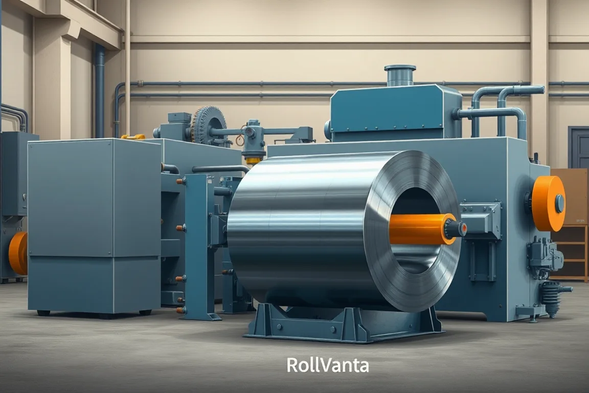
A hydraulic decoiler is a coil payoff device whose mandrel or arbor is expanded by hydraulic pressure to grip the inside diameter of a coil and support it during unwinding. Its primary job is to hold the coil securely, rotate it under control, and feed strip into the next operation without introducing scratches, edge damage, or uncontrolled spillage. It is not a leveler, not a slitter, and not a cut-to-length machine. When a line requires flatness correction, width reduction, or length control, those are separate operations that may be placed after the decoiler but are not part of its function. Treating the decoiler as a general coil processing center can lead to an undersized or incomplete installation.
The finished profile: what the decoiler must be able to accept
The finished profile is the set of coil and strip attributes the decoiler must handle. At minimum, the profile should state coil width, base-metal thickness, coil mass, inside diameter, outside diameter, and the required delivered form, such as a continuous strip or a blank. Thickness and width are not sufficient on their own because grade and strength influence the torque needed to unwind and the tendency of the coil to expand or telescope. Surface condition also matters: painted, coated, polished, or soft materials may require special contact surfaces or non-marking rollers. A hydraulic decoiler designed for a narrow, light coil may not have the mandrel reach, bearing capacity, or braking torque for a wider, heavier coil, even if the hydraulic expansion is powerful enough to grip it. The profile is therefore a capacity envelope, not a single point rating.
Interfaces with upstream and downstream equipment
The decoiler rarely operates alone. Its mechanical interface includes the coil car or loading device that places the coil on the mandrel, the hold-down or snubber that controls the outer wraps, the peeler or threading device that guides the lead end into the line, and the foundation or floor plates that carry the load. Its electrical interface includes the power supply for the hydraulic pump and controls, plus any signals exchanged with the line controller for tension, speed, or direction. A frequent oversight is the strip accumulator or loop pit that buffers speed differences between the decoiler and the downstream process. Without adequate buffering, the decoiler may start and stop repeatedly, which can mark the strip, stress the mandrel, and shorten component life. The user should request a layout showing every interface and who supplies each item. Omissions in material handling, threading, and scrap removal can make a low purchase price misleading.
Production route: from coil to accepted output
A typical production route for a line using a hydraulic decoiler follows a sequence: safe coil loading, payoff, leveling or slitting, length control or recoiling, and handling of finished product and scrap. Safe coil loading means the coil is brought to the mandrel with a coil car or crane and held until the mandrel expands and the hold-down engages. Payoff is the controlled unwinding of the coil as strip is pulled into the line. If leveling is required, a leveler corrects flatness; if slitting is required, a slitter cuts the strip into narrower widths. Length control may be a cut-to-length shear or a recoiler that winds the processed strip. Handling includes stacking sheets, banding coils, removing scrap, and moving finished bundles. Each step has its own tooling and setup. The decoiler only handles the payoff portion; its performance should be judged by whether it delivers strip to the next operation without damage and without interrupting the line.
Tooling alternatives and configuration choices
Hydraulic decoilers come in several mechanical arrangements. A cantilevered mandrel is common for lighter coils and allows easy loading from one side. A double-support mandrel, with a bearing on both ends, is better for heavy or wide coils because it resists deflection and reduces vibration. Some decoilers have a fixed mandrel diameter and use hydraulic expansion to grip a range of inside diameters; others use interchangeable sleeves or adapter plates for different core sizes. The choice depends on how often the coil inside diameter changes and how much changeover time is acceptable. Braking and tension control also differ: a simple hydraulic brake may be adequate for low-speed feeding, while a motorized payoff with dancer or load-cell feedback is needed when strip tension must remain consistent across a range of coil diameters. The user should compare alternatives based on the actual coil mix, not on a single ideal coil. A decoiler that is flexible enough for occasional odd sizes may be less rigid for steady production of one size, and vice versa.
Separate operations: leveling, slitting, cut-to-length
Leveling, slitting, and cut-to-length are distinct processes that answer different quality problems. Leveling changes flatness by bending the strip through a series of rolls; it does not change width or length. Slitting creates narrower strips by passing the coil through rotary knives; it changes width and produces edges whose burr and straightness must be inspected. Cut-to-length produces sheets or blanks by measuring and shearing the strip; it changes length and requires attention to squareness and dimensional consistency. A hydraulic decoiler can feed any of these operations, but it cannot perform them. When reviewing a quotation, separate the decoiler scope from the leveler, slitter, shear, and recoiler scope. This prevents the common error of assuming that a decoiler package includes all the equipment needed to make a finished part.
Changeovers and setup between coil sizes
Changeover time is a real production cost. When the coil inside diameter changes, the mandrel may need different expansion segments or a different sleeve. When coil width changes, the hold-down and guide positions may need adjustment. When thickness or grade changes, the braking or tension settings may need to be reset. Some of these adjustments can be done with quick-release features, while others require tools and measurements. The user should ask for a written changeover procedure that lists each step, the tools required, and the expected setup scrap. That information is more useful than a general claim of fast changeover. Setup scrap is the material wasted while the line is brought to steady quality; it should be measured during a trial with the actual coil profile. Changeover also affects safety: any adjustment near the mandrel or moving strip should be done with the equipment stopped and isolated according to the manufacturer's procedures.
Inspection and accepted output
Inspection should begin with the incoming coil and continue through the finished product. For the decoiler itself, inspect the mandrel for wear, the hydraulic system for leaks, the hold-down for proper contact, and the controls for correct response. For slitting, inspect strip width, edge burr, and recoiling quality. For cut-to-length, inspect length, squareness, and flatness. It is important to define how incoming coil defects, such as edge cracks, rust, or thickness variation, are distinguished from damage caused by the decoiler or downstream process. This distinction should be agreed before acceptance testing. A first-off piece and a representative steady-production sample should be measured with the agreed gauges. The accepted output is not simply a maximum speed; it is the quantity and quality of product that can be produced per shift with the actual profile and material.
Checklist for specifying a hydraulic decoiler
- State the full coil profile: width, thickness, grade, mass, inside diameter, outside diameter, and surface condition.
- Describe the required delivered form: continuous strip, slit strip, or cut blanks.
- List every upstream and downstream operation and identify the equipment that performs each one.
- Request a layout showing the decoiler, coil car, hold-down, peeler, and any loop or accumulator.
- Confirm the electrical supply: voltage, frequency, and phase, and request an equipment schedule for installed power.
- Define the acceptance checks for the finished product and the method for distinguishing incoming defects from process damage.
- Ask for a written changeover procedure with tools, steps, and expected setup scrap.
- Clarify what material handling, scrap removal, and safety guarding are included in the quotation.
- Plan a trial run with the agreed material and profile, not an easier substitute.
- Record changeover steps, setup scrap, and unloading time during the trial.
Practical comparison of alternatives
When comparing hydraulic decoilers from different suppliers, focus on measurable differences. A cantilevered mandrel may be cheaper and easier to load, but a double-support mandrel is likely to handle heavier coils with less deflection. A fixed-expansion mandrel may be simpler, while an interchangeable-sleeve design may reduce changeover time for varied core sizes. A manual hydraulic brake may suffice for low-speed, constant-thickness feeding, but a motorized payoff with tension feedback may be necessary for consistent quality across a range of coil diameters. The trade-offs are real: more flexibility often means more complexity and higher cost, while a dedicated design may be more rigid and productive for a narrow product range. The user should match the alternative to the actual production plan, not to a hypothetical maximum.
Why the decoiler is only part of the line
It is tempting to focus on the decoiler because it is the first machine in the line, but the quality of the finished part depends on the whole process. A well-chosen decoiler that feeds a poorly adjusted leveler or a worn slitter will still produce unacceptable output. Conversely, an adequate decoiler can support excellent results when the downstream operations are properly tooled and maintained. For this reason, the specification should consider the decoiler in the context of the complete production route. The user should ask how the decoiler's payoff performance affects the next operation, and how the next operation's requirements feed back to the decoiler's tension and speed control. This system view prevents isolated optimization that does not improve the final product.
FAQ
What is the difference between a hydraulic decoiler and a mechanical decoiler?
A hydraulic decoiler uses hydraulic pressure to expand the mandrel and grip the coil inside diameter, while a mechanical decoiler may use manual screws, cams, or other mechanical means. Hydraulic expansion can make loading and unloading easier and can provide more consistent gripping force, but it also requires a hydraulic power unit and adds maintenance considerations. The choice depends on coil weight, changeover frequency, and the available infrastructure.
Can a hydraulic decoiler handle coils with different inside diameters?
It can, if the mandrel is designed with a sufficient expansion range or with interchangeable sleeves. The user must specify the full range of inside diameters required, and the supplier must confirm that the decoiler can grip each size safely. A decoiler that grips one inside diameter well may not grip a much larger or smaller one without additional tooling.
How do I determine the required braking or tension for my application?
The required braking or tension depends on coil mass, strip width and thickness, the speed of the line, and the tendency of the coil to unwind. These factors should be reviewed with the equipment supplier. In general, heavier and wider coils require more braking capacity, and consistent tension is more critical when the strip is thin or when the downstream process is sensitive to speed variation.
What should be included in a trial run for a hydraulic decoiler?
A trial run should use the actual coil profile and material, not a substitute that is easier to process. It should include loading, threading, running at production speed, and unloading. The trial should record changeover steps, setup scrap, and any quality issues. First-off pieces and a steady-production sample should be measured with the agreed gauges. The trial should also confirm that safety features function as intended.
How can I distinguish incoming coil defects from damage caused by the decoiler?
Before the trial, agree on a method for documenting incoming coil condition, such as photographs or measurements at the coil ends. During the trial, inspect the strip immediately after payoff and compare it with the documented condition. Any new marks, scratches, or edge damage that appear after the decoiler can be attributed to the decoiler or downstream equipment. This distinction should be part of the acceptance criteria.
What information should I request from a hydraulic decoiler supplier?
Request a written equipment scope that lists the decoiler and all associated items such as coil car, hold-down, peeler, and hydraulic power unit. Ask for a layout drawing, an equipment schedule for installed power, and a changeover procedure. Request acceptance criteria for the finished product and a plan for a trial run with the actual material. Also clarify what documentation, training, and spare parts are included.

Continue your research
- Coil Processing & Auxiliary Equipment
- Steel Coil Slitting Line
- Cut To Length Line
- Narrow Strip Steel Coil Slitting Line
- High Speed Steel Coil Slitting Line
- Heavy Gauge Steel Coil Slitting Line
- How Coil processing line Works
- How To Choose a Coil processing line
- Coil processing line Price: What Affects the Cost?
Configuration & specification inputs
Match the configuration to your section drawing, material and production requirements.
| Parameter | Requirement / confirmation needed |
|---|---|
| Profile geometry | A hydraulic decoiler provides supported coil payoff within a defined capacity envelope. Coil mass, width, inside diameter and outside diameter are all necessary; hydraulic expansion is not a substitute for a capacity review. |
| Material | Defined coil grades and surface conditions within a verified capacity envelope |
| Thickness & grade | Buyer to specify base-metal thickness and grade; operating range requires supplier verification. |
| Process route | Safe coil loading → payoff → leveling or slitting → length control/recoiling → handling |
| Cutting | Confirm profile-supported cutoff, cut lengths, end quality and any secondary operations. |
| Output | Define accepted output per shift with the actual profile and material. |
| Electrical supply | Buyer to state voltage / frequency / phase. Installed power requires a confirmed equipment schedule. |
| Acceptance | Verify the agreed hardware, controls, guarding, documentation and connection interfaces against the equipment scope. Follow the manufacturer's procedures for installation and use. Coil handling involves stored energy and heavy loads that require a properly defined operating arrangement. |