
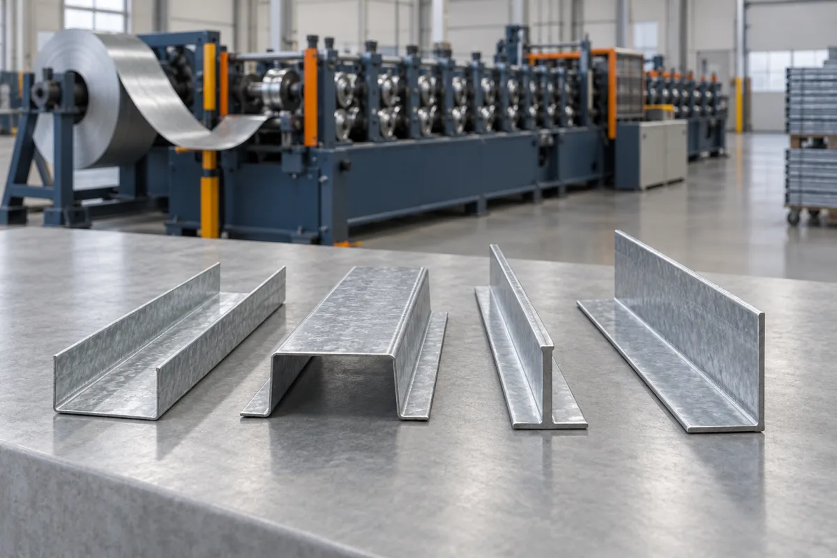
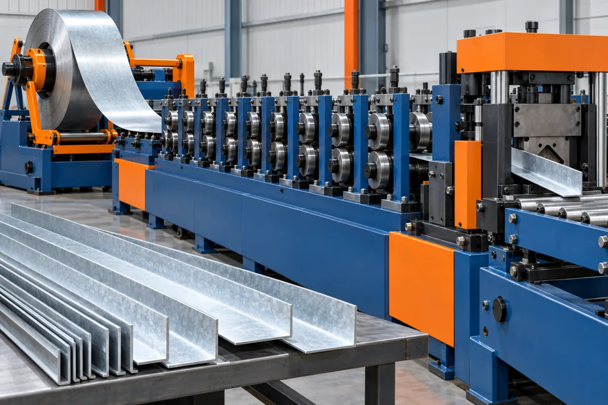
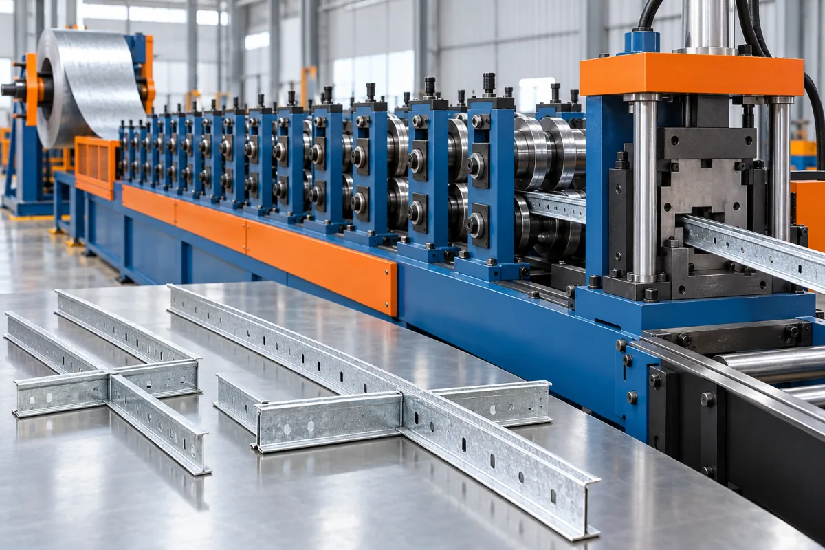
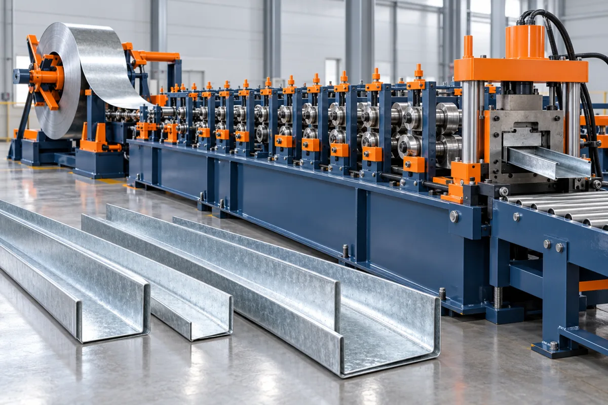
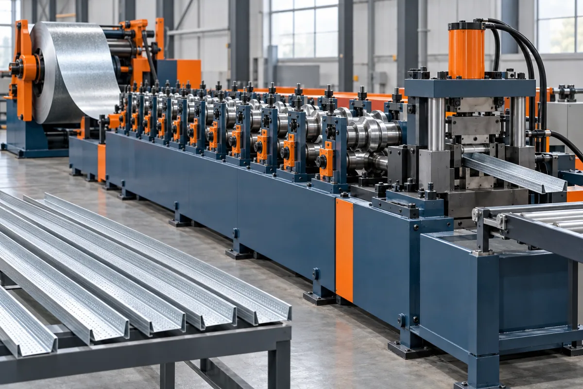
Ceiling and furring roll forming equipment produces members that work inside a specified suspension or lining system. Main channels, furring channels, T-grid members and perimeter wall angles perform different functions. The equipment choice should follow those components and their connectors rather than treating every small ceiling section as a variation of one channel.
Identify the component's position in the ceiling
Begin with an assembly drawing showing what the member supports, what supports it and which parts connect to it. This establishes the functional faces, openings and end features. A visually similar section can be unsuitable if the clip, hanger or grid connection is different.
- Furring channels: review lining support, bearing faces and the specified attachment interfaces.
- Main channels: define the system-specific suspension and connections to secondary members.
- T-grid: coordinate visible faces, repeated module lengths and end connectors.
- Wall angles: specify perimeter geometry, finish and the required ceiling interface.
Specify the complete section, not only its name
Provide dimensions, bend radii, returns and functional references. Include the clip or connector used for assembly approval. A section called main channel in one market need not match another ceiling system using the same description.
For grid components, the repeated module and end details deserve particular attention. Producing a straight central section is not necessarily the same as delivering a member that joins correctly into the intended grid. Assign responsibility for connector manufacture or supply.
Separate plain forming from feature and assembly operations
List holes, slots, embossments, end preparation and any combined construction required by the product. Establish which are made in-line and which are separate. A former for plain channel should not be compared as equivalent to a complete grid-member production system.
Where the visible face has a particular material or finish, include it in the route. Identify how it is protected and how the completed component is inspected after any joining or additional processing.
Use production-intent material and meaningful changeovers
Specify grade, thickness convention, coating and material combinations for each member. Thin sections and small returns need trials that represent the actual stock. Keep material identity with the approved samples rather than assuming one demonstration covers every finish or grade.
For several sizes, identify the roll, guide, punch and cutting changes. Measure recovery through the first accepted component and mating connection. A width adjustment alone does not prove that every associated feature follows the new geometry.
Check the assembled system interfaces
Trial representative members with the intended connectors, hangers or perimeter parts. Inspect fit, module references and end condition without local modification that conceals a deviation. Use the agreed support method for slender sections so straightness measurements are comparable.
Appearance and functional fit are separate acceptance concerns. A clean visible face cannot compensate for an incorrect end connector, while a fitting member can still have unacceptable surface damage. Both should be included where relevant to the product.
Plan accepted-component output
Measure completed acceptable parts over the real mix of lengths and features. Repeated end operations, sorting and packaging can determine delivery more than strip travel speed. Include these stages when comparing quotations and layout options.
Prepare the component drawings, material schedule, mating samples, module requirements and normal orders before requesting a configuration. The detailed pages below distinguish each member's tooling and inspection needs so a ceiling-equipment package can be matched to one coherent product system.
Continue your research
- Furring Channel Roll Forming Machine
- Main Channel Roll Forming Machine
- Ceiling T Grid Roll Forming Machine
- Wall Angle Roll Forming Machine
- Hat Furring Channel Roll Forming Machine
- Ceiling Carrying Channel Roll Forming Machine
- Ceiling T Main Runner Roll Forming Machine
- Ceiling Cross T Roll Forming Machine
- Omega Ceiling Profile Roll Forming Machine
- How Ceiling roll forming machine Works
- How To Choose a Ceiling roll forming machine
- Ceiling roll forming machine Price: What Affects the Cost?
- Materials and Thickness for Ceiling roll forming machine
- Production Speed and Output of Ceiling roll forming machine
- Roller, Tooling and Forming Design for Ceiling roll forming machine
- Common Defects and Troubleshooting for Ceiling roll forming machine
- Maintenance Checklist for Ceiling roll forming machine