
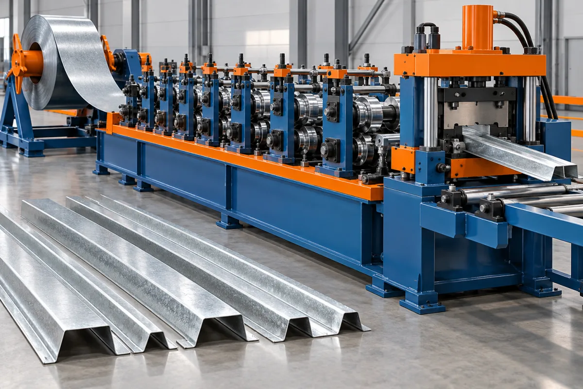
An omega ceiling profile roll forming machine makes a hat-like lightweight section used in the specified ceiling support arrangement. The central face, sidewalls and outward feet form a recognizable outline, but the exact returns and connection surfaces determine whether it fits the selected system. Omega is therefore a useful family name, not a complete tooling specification.
This product should be distinguished from structural omega purlins and from other ceiling channels with different roles. The machinery brief needs the actual ceiling-profile drawing, material and mating components. Similar appearance does not establish shared tools or interchangeable parts.
What is the omega profile's role in the ceiling?
Identify whether the member supports lining directly or connects to another ceiling component in the selected arrangement. Show its installed orientation, contact surfaces and attachment details. The system drawing should establish the role before the section is translated into a machine requirement.
Where clips engage the feet or returns, provide their drawings and samples. A small hidden dimension can govern fit even when overall width and height are correct. The line should be approved against that interface, not only the outline.
Which section dimensions matter?
Define face width, total width, depth, sidewall angles, foot widths and any curls or lips. Mark the inspection datums and the surfaces intended to lie in a common plane. Include material thickness and bend radii.
- Separate projected width from developed input width.
- Identify symmetric and asymmetric features.
- Show clip-contact openings and returns.
- Specify any ribs or surface texture.
- Define stock lengths and acceptable end condition.
Use an undamaged reference sample if matching an established product, but resolve differences between it and the drawing before tools are made.
How does this differ from hat furring?
The names may overlap in some markets, but the selected ceiling system determines the actual shape and purpose. Compare the full section and connections rather than assuming that omega and hat furring always describe the same component.
If two named products are genuinely identical, one controlled drawing can establish that. If their feet, depth or clips differ, maintain separate product references and acceptance samples. This prevents naming conventions from hiding a real manufacturing difference.
How is the lightweight section formed?
Coil entry guides present strip to successive stages that develop the crown, sidewalls and feet. Any texture, bead or punched feature is included at the agreed point in the route. The cutoff produces lengths for supported transfer and bundling.
Review support around tight returns and open feet. Thin profiles can change shape during cutting or handling even when the forming tools produce the correct section. Inspect at more than one stage to identify where any deviation appears.
What should be specified about the material?
State grade, base-metal thickness and coating with a clear measurement convention. Include the actual material in clip-fit trials. An apparently small thickness change can alter a close engagement and should not be treated as automatically equivalent.
Inspect bends, texture and cut edges. Keep coil identification and approved samples with the setup reference. If several material combinations will be sold, include representative cases in the trial matrix rather than approving only the easiest one.
How can sizes or returns be changed?
Ask which dimensions adjust within the proposed tooling and which require replacement parts. Crown width, depth and foot position may be linked. A new return can also require different cutting support or a different clip reference.
Demonstrate the first acceptable profile after a change using both measurements and the intended mating components. Reaching the target outside width does not prove that the connection opening has recovered correctly.
How should channels be packed without changing fit?
Define stack orientation, bundle supports and restraints using actual profiles. The feet and returns should not be forced into a different position by normal packaging. Check that members separate from the bundle without damage.
For multiple ceiling systems, keep identity clear. Similar omega profiles can have different connector requirements, and mixing them creates problems that dimensional quality alone cannot prevent. Labels should remain associated with the correct bundle.
What should acceptance demonstrate?
- Confirm the product role, section and material.
- Measure crown, feet, returns and depth without unintended restraint.
- Inspect end condition and any surface features.
- Fit the specified clips or support components.
- Demonstrate normal lengths and required size changes.
- Recheck geometry after bundling.
- Record accepted pieces and startup waste.
Keep ceiling load, fire and acoustic requirements with the complete system's design and assessment. Manufacturing a correct omega profile does not by itself establish those assembly-level properties.
Frequently asked questions
Is omega a standardized ceiling profile?
The name alone does not establish one universal section. Obtain the drawing and intended connection references for the specific ceiling system.
Can an omega purlin machine make it?
Only after reviewing the much more specific section, material and handling requirements. Similar shape does not prove suitable tooling or control for a lightweight ceiling component.
Why use actual clips during trials?
Clip fit depends on hidden returns and openings that overall dimensions may not fully describe. Actual mating components connect measurement to the intended assembly.
Can the feet be forced flat during inspection?
Use the agreed measurement method and avoid restraints that conceal delivered shape. The purpose is to establish whether the part fits normally, not whether a fixture can reshape it.
What should the enquiry contain?
Provide the section and ceiling-interface drawings, material specification, lengths, clips and required variants. Add texture and bundle requirements where relevant.
Define the actual ceiling interface
An omega-profile line should make a repeatable component for a specified ceiling arrangement. Clear contact geometry, material and packaging checks turn a familiar shape into a useful manufacturing specification.

Continue your research
- Ceiling & Furring Roll Forming Machines
- Furring Channel Roll Forming Machine
- Main Channel Roll Forming Machine
- Hat Furring Channel Roll Forming Machine
- Ceiling Carrying Channel Roll Forming Machine
- Ceiling T Main Runner Roll Forming Machine
- How Ceiling roll forming machine Works
- How To Choose a Ceiling roll forming machine
- Ceiling roll forming machine Price: What Affects the Cost?
Configuration & specification inputs
Match the configuration to your section drawing, material and production requirements.
| Parameter | Requirement / confirmation needed |
|---|---|
| Profile geometry | System-specific omega crown, depth, sidewalls, feet and functional returns. |
| Material | Specified lightweight steel grade and coating with clear installed orientation. |
| Thickness & grade | Approved base-metal thickness combinations for the selected section and clip fit. |
| Process route | Guided entry, required texture or features, omega forming, protected cutting and bundling. |
| Cutting | Required lengths with undistorted feet, returns and usable ends. |
| Output | Accepted ceiling profiles including connection checks and normal packaging. |
| Electrical supply | Utilities for the selected lightweight forming and auxiliary-equipment package. |
| Acceptance | Crown and foot geometry, connector openings, intended clips and retained fit after bundling. |