
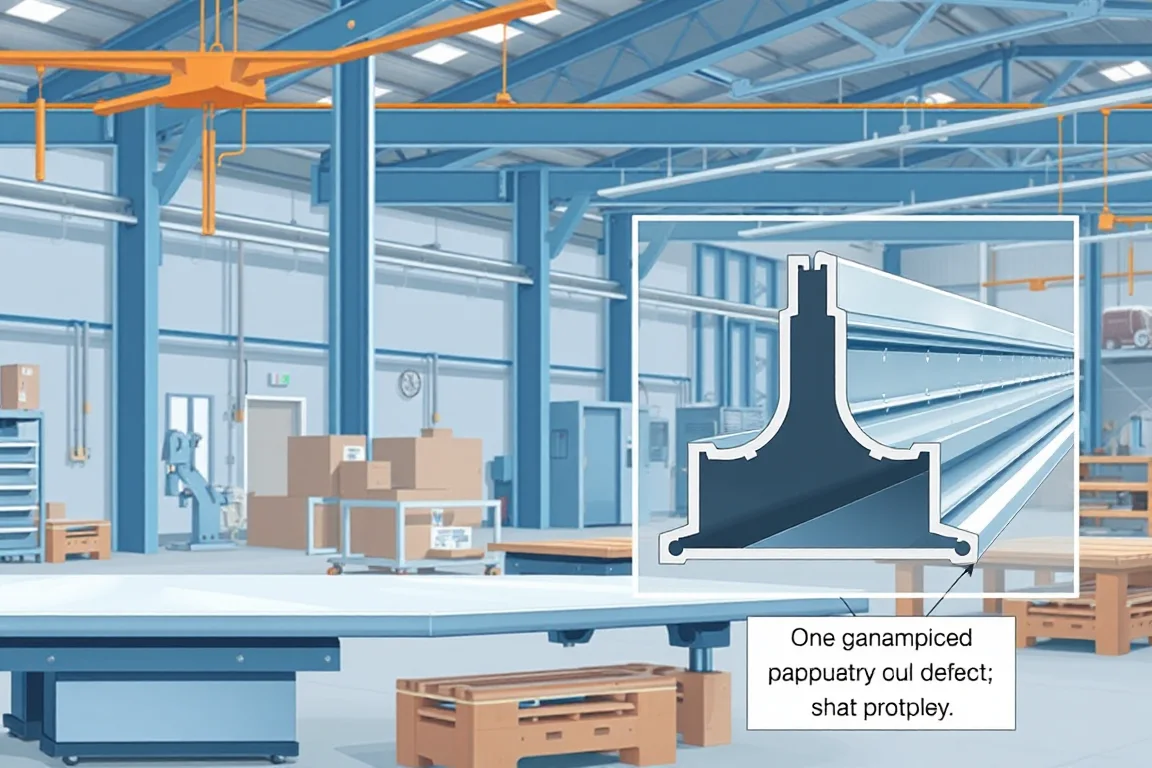
Ceiling-component troubleshooting should distinguish the longitudinal section from its features, connectors and visible finish. A cross tee that will not engage may have an end-detail problem even when the roll-formed body is correct. A marked face may be damaged during packing rather than forming. Locating the relevant interface prevents unnecessary changes to unrelated tooling.
Identify the complete component and mating system
Record the component drawing, material streams, feature pattern and connector revision. Confirm that the mating hanger, runner or cross member belongs to the same approved system. Similar nominal widths do not establish interchangeability.
Retain identified samples and note recent material, profile, connector or packing changes. A photograph of one loose piece rarely supplies enough information. The investigation needs the assembly relationship and the process history.
When a cross connection will not engage
Inspect both the receiving feature and the end connector using the approved datums. Determine whether interference comes from geometry, position, local deformation or an incompatible component. A correct runner body does not automatically clear its connection details.
Use the specified assembly procedure and record any forcing or local alteration needed. Do not modify connectors merely to demonstrate fit. Corrections should follow the responsible quality and engineering review.
When the assembled grid does not align
Check the relevant component lengths, slot positions and end references. A repeated spacing error can accumulate across an assembly even when individual features appear regular. Compare measured values with the controlled system drawing.
Separate manufacturing evidence from the support and installation condition. If components meet their criteria but an assembly remains misaligned, investigate the interface and setup rather than assuming one roll adjustment will solve the whole system.
When a channel does not fit its hanger or clip
Verify the correct channel and mating hardware first. Measure bearing flanges, returns and the defined contact geometry. A similar-looking replacement clip may not be compatible with the approved section.
Inspect after cutting and handling. Thin flanges can be bent during collection, creating a local fit problem absent at the mill exit. Comparing those boundaries helps locate the source before changing forming tools.
When the visible cap is misaligned or marked
For capped construction, distinguish cap-to-body alignment from scratches or other appearance damage. Inspect at defined points after forming or joining, cutting and packing. Record the cap material and finish identity.
Use agreed viewing conditions and preserve samples showing where the issue first appears. Cleaning or inspecting machinery must follow approved isolation procedures. Never reach into a moving cap feed or forming path to trace a mark.
When slots or holes are misplaced
Check the requested pattern, reference end and final-component datums. A clean feature can be at the wrong coordinate. Record individual requested and measured positions to distinguish a constant shift from a length- or sequence-related issue.
Avoid informal offsets that make one sample fit without explaining the cause. Verify authorized corrections across the relevant component lengths and connection patterns. Keep the approved product design intact.
When ends or returns are damaged
Inspect immediately after cutting and again after collection. Confirm correct section-specific tools and supports through the setup record. Local damage can originate at either boundary, and the remedy should match the evidence.
Keep length accuracy separate from end condition. A runner may have the correct total length but an unusable connector or distorted bearing flange. Complete-component acceptance needs both geometry and functional fit.
When packages contain mixed or incomplete components
Trace counts, labels and connector-completion status through the route. A runner awaiting an end operation can be mistaken for finished stock if identification is lost. Physical forming quality cannot compensate for that workflow error.
Use a controlled mixed order to verify corrective changes. Confirm that main runners, cross members and other variants retain the right identities and quantities at final release. Correcting a label for new work does not automatically clear previously packed material.
Verify the entire interface after correction
Define the affected production interval before releasing held packages. A correction to one connector tool establishes the new condition but does not prove the contents of earlier bundles. Use coil, setup and packaging records to identify which components need inspection or another disposition. Where traceability is incomplete, document that limitation instead of assuming that only the last visible reject was affected. This connects troubleshooting to the actual customer order and prevents a resolved machine issue from leaving unresolved product in stock.
Preserve the original sample, document the authorized change and inspect the complete component. Assemble the specified mating interface and check finish after normal handling. A local improvement that damages another feature is not a complete recovery.
- Confirm the defect against the component and system references.
- Locate the earliest process boundary showing it.
- Review material, feature, connector and handling changes.
- Apply an approved action through qualified personnel.
- Verify geometry, fit, finish and package identity.
- Trace affected prior production and record disposition.
For example, if only one cross-member batch fails to engage a known accepted main runner, compare its connector and end references with an accepted cross member. This controlled swap can narrow the issue before the team alters the main-runner forming tools. Keep the result documented rather than relying on a verbal observation.
Frequently asked ceiling troubleshooting questions
Does poor cross-tee fit always mean the main runner is wrong?
No. Receiving slots, end connectors, component identity and local damage all need checking. Use identified mating samples to isolate the interface.
Can a damaged connector be bent back routinely?
Use the responsible product disposition process. An informal repair may change the approved connection and should not be treated as automatic acceptance.
Why distinguish cap alignment from scratches?
They can originate in different operations and require different evidence. One concerns the construction relationship; the other may involve contact or handling damage.
What information helps technical support most?
Component and interface drawings, material identities, annotated measurements, mating samples and a timeline of changes. Include photographs at consistent process boundaries rather than only a finished assembly.
Continue your research
- Ceiling & Furring Roll Forming Machines
- Furring Channel Roll Forming Machine
- Main Channel Roll Forming Machine
- Hat Furring Channel Roll Forming Machine
- Ceiling Carrying Channel Roll Forming Machine
- Ceiling T Main Runner Roll Forming Machine
- How Ceiling roll forming machine Works
- How To Choose a Ceiling roll forming machine
- Ceiling roll forming machine Price: What Affects the Cost?