
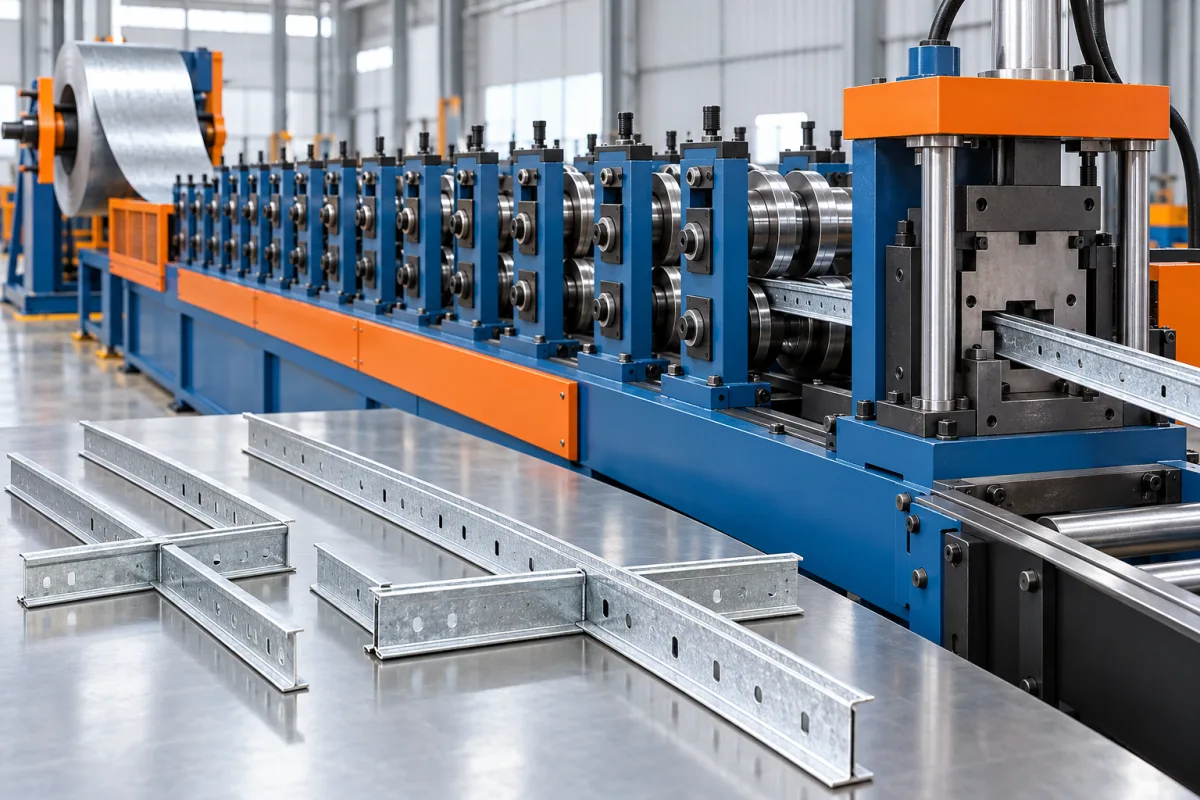
A ceiling T grid roll forming machine produces the runners and cross tees that create a modular suspended-ceiling framework. Unlike a simple open channel, a T-grid member combines a supporting section, a visible lower face and connection details that must locate adjoining members accurately. The finished ceiling depends on all three working together.
The production project should begin with the complete grid family. Main runners, cross tees and perimeter trims have different jobs, lengths and end details. A machine proposal needs to show which members it makes, how their connectors are produced and how the resulting pieces assemble into the intended module.
What makes a T-grid member a technical profile?
The lower face supports the edge of the selected ceiling tile or panel and remains visible in an exposed-grid system. The upright portion supplies the defined section geometry and carries openings or connection features. End connectors and intermediate slots establish the relationship between members.
That combination makes the product more than a metal strip bent into a T. A visually attractive face is insufficient if cross tees do not engage, while a sound connection is insufficient if adjacent visible faces form uneven lines. The specification should address section, appearance and assembly together.
How do main runners and cross tees differ?
Main runners form the principal repeated lines of the selected grid and include the interfaces required by the suspension and connecting members. Cross tees complete the module between those lines. Their connector patterns and end relationships can differ even when their exposed face width appears identical.
List each member by drawing rather than by length alone. Two cross tees with equal lengths can have incompatible end connectors, and a main runner may contain a different slot schedule from a shorter member. The machine's control and tooling scope must follow the complete product family.
Perimeter angles or other boundary trims are another product category. Include their manufacture separately instead of assuming that a T-grid line automatically produces every accessory needed to finish a ceiling.
Which construction and visible-face arrangement is required?
Specify how the structural body and exposed face are made. Some grid designs combine a formed body with a separate finished cap; other constructions need their own production review. Where more than one strip is involved, the route must coordinate their feeding, forming and joining or retention.
Identify the visible-face material, color, finish and protective requirements. Its alignment with the body matters at joints and cut ends. A proposal should explain how the cap or facing remains positioned during production and how the finished product is inspected for marks or irregular edges.
Do not assume that changing the face width is a minor cosmetic option. It can alter tools, joining details, tile support and connection geometry. Review each required visible-face family as part of the complete system.
What should the drawing package include?
- Section drawings: body, lower face, returns and any reinforced or closed portions.
- Member schedule: main runners and each cross-tee type with finished lengths.
- Connections: end details, intermediate slots, engagement references and mating components.
- Suspension: the defined interfaces required by the selected ceiling system.
- Appearance: visible-face dimensions, color and inspection conditions.
- Assembly: intended module, tile or panel relationship and perimeter arrangement.
Use production-intent connectors and mating members during review. A photograph of a ceiling cannot show the hidden engagement details that determine the tooling and feature-making route.
How is a T-grid member manufactured?
The actual sequence depends on the selected profile and connector design. It can involve preparation of body and facing strip, progressive forming, controlled combination of those elements, feature-making, end processing, cutoff and packaging. Each proposal should identify the sequence it uses and which operations remain separate.
- Prepare the specified body and visible-face materials.
- Develop the section while controlling the relationship between its upright and supporting face.
- Produce the required openings and connection features.
- Make or attach the specified end connectors where included.
- Cut and finish the member ends to the approved geometry.
- Inspect dimensions, engagement and appearance before packing.
The coordination of features with cut length deserves particular attention. The module is established by functional connection datums, which may not be represented adequately by measuring only the overall loose-member length.
Integral connectors or separately attached connectors?
An integral connector is developed from the member's own material and therefore brings its forming or stamping requirements into the profile route. A separate connector introduces another component and an attachment operation. Both arrangements need a defined connection drawing and assembly test.
Compare the complete process, including connector supply, alignment, attachment inspection and scrap handling. An apparently simpler profile line may rely on significant secondary work. Conversely, an integrated connector route may require dedicated tooling that limits changes to another connection family.
Do not assume that connectors from different grid systems are interchangeable because they enter a slot. Engagement, release behavior and the assembled geometry must match the intended system design. Use the exact combination specified for the product.
Why does feature pitch matter more than a nominal module label?
The visible ceiling pattern depends on the relationship between slots, end engagements and member lengths. A repeated pitch error can accumulate across an assembled grid even if individual profiles look acceptable. Define the functional datums and measurement sequence before approving the feature tools.
Assemble several modules using trial members and the intended connection method. Check alignment, module dimensions and the meeting of exposed faces. Include joints in both directions rather than evaluating a single isolated connection.
If a module is incorrect, measure the contributing members and engagement positions separately. Changing one overall length to make a sample grid fit can conceal an incorrect connector or slot reference elsewhere.
How should appearance be assessed?
Agree the visible surfaces, lighting and viewing conditions used for inspection. Check scratches, face alignment, edge condition and the relationship between adjacent members. Different colors or finishes may make the same handling mark more or less noticeable, so use the intended materials in trials.
Inspect before and after normal packaging. Damage introduced while nesting or boxing should not be confused with forming marks. The packing arrangement must protect both the finished face and vulnerable end connectors during routine movement.
What configuration changes need demonstration?
Separate length changes, slot-pattern changes, connector changes and section changes. The controller may handle some variations, while others require tools or another production route. Ask for a capability matrix covering every main-runner and cross-tee family in the proposed catalogue.
Demonstrate a commercially relevant transition and the recovery of accepted production. Include connector inspection and an assembled module after the change. A successful length command does not prove that the corresponding end and intermediate features moved to the correct functional positions.
How should output and packing be compared?
Use accepted members of each type and complete saleable packs as the output measures. Connector processing, inspection and packaging can govern the rate even when forming itself is fast. Compare a representative mix rather than only the easiest long member.
Specify carton quantities, orientation, protection and labels. If automated boxing is proposed, test the actual member and connector combination. A package that counts correctly but damages the exposed face or deforms the ends does not deliver useful production output.
In quotations, separate body forming, face handling, feature tools, connector operations, inspection and packing. This makes different levels of integration comparable and reveals which purchased components or manual operations remain outside the line.
What should acceptance prove?
- Cross-section and face alignment for each agreed member family.
- Functional length, feature pitch and connector position.
- Engagement of production-intent main runners and cross tees.
- Dimensions and appearance of an assembled multi-module grid.
- Correct recovery after a required product change.
- Surface and connector condition after normal packing.
- Accepted quantities, rejected pieces and remaining deviations.
Keep manufacturing acceptance separate from the completed ceiling system's required performance evidence. The trial should confirm that the line makes the specified components consistently, while system design and qualification remain explicitly assigned project responsibilities.
Frequently asked questions
Can one line make main runners and cross tees?
A suitable configuration can cover the agreed family, but the tooling, feature patterns and connector operations must be specified. Do not infer complete coverage from a shared T-shaped cross-section.
Are T-grid connectors universal?
No. Connection geometry and engagement behavior vary. Use the intended main-runner and cross-tee combination during development and acceptance. Entering the same-looking slot is not sufficient proof of compatibility.
Does the line also make ceiling tiles?
Not unless tile or panel production equipment is separately included. Grid members and the supported panels have different manufacturing routes. Define the project boundary so a framework line is not mistaken for a complete ceiling factory.
Why inspect a complete module?
It combines the effects of feature pitch, end connectors and member length. Individual dimensions remain necessary, but an assembled check reveals whether those dimensions produce the intended grid and visible joint alignment.
Can the face color be changed without other adjustments?
A material or finish change should be reviewed for feeding, surface protection and packing. The geometric tools may remain the same for an equivalent facing, but the production trial should confirm appearance with the actual material.
What should an enquiry contain?
Provide every member and connector drawing, material and finish specification, module layout and packing requirement. Include the expected product mix. These inputs define a T-grid production system rather than a generic profile former.

Continue your research
- Ceiling & Furring Roll Forming Machines
- Furring Channel Roll Forming Machine
- Main Channel Roll Forming Machine
- Hat Furring Channel Roll Forming Machine
- Ceiling Carrying Channel Roll Forming Machine
- Ceiling T Main Runner Roll Forming Machine
- How Ceiling roll forming machine Works
- How To Choose a Ceiling roll forming machine
- Ceiling roll forming machine Price: What Affects the Cost?
Configuration & specification inputs
Match the configuration to your section drawing, material and production requirements.
| Parameter | Requirement / confirmation needed |
|---|---|
| Profile geometry | T-grid body, exposed face, end connectors and intermediate feature schedule |
| Material | Specify body and visible-face materials separately where the construction uses multiple strips |
| Thickness & grade | Review body and cap thicknesses with the approved section and connection design |
| Process route | Material preparation, section and face forming, connection features, end processing, cutoff and packing |
| Cutting | Reference finished length to functional connector and slot datums |
| Output | Accepted main-runner and cross-tee packs for a representative product mix |
| Electrical supply | Confirm utilities for forming, connector operations, inspection and packaging as quoted |
| Acceptance | Check section and face alignment, assemble several grid modules and verify connector condition after packing |