
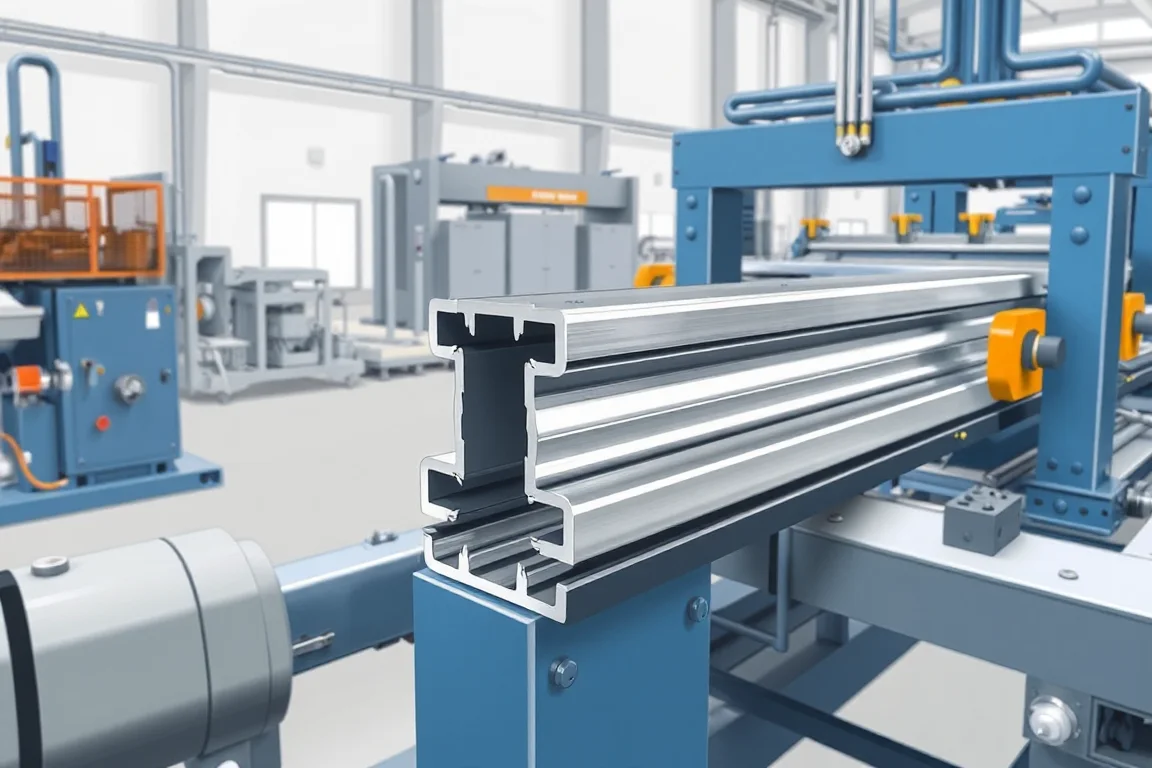
A ground mount solar post roll forming machine produces a specified cold-formed steel post for a photovoltaic support structure. The post may have a C, U, sigma or another approved section, and its connection and end details depend on the selected foundation and mounting design. The machine should not be chosen from the phrase solar post alone.
This route makes a controlled structural component. It does not determine embedment, soil suitability or foundation capacity. Those project requirements establish the post drawing that the manufacturing equipment must reproduce.
Which post construction is required?
Provide the complete cross-section, material, length and end geometry. Identify open sections, returned edges and any additional fabrication. A roll-forming route should be proposed only where it suits that actual component.
Distinguish the post from a ground screw or other foundation product. A cold-formed post line does not automatically manufacture helical blades, welded piles or every ground-mount foundation type. The equipment boundary should be explicit.
How does the foundation design affect the drawing?
The approved project design determines the member length, end preparation and connection zone. Supply those requirements as controlled inputs. Do not ask the equipment supplier to infer a universal post from an assumed soil condition.
Where several project variants are needed, keep their identities separate. Two posts with the same section may have different lengths or upper hole patterns and should remain distinguishable throughout production.
Which upper connections must be specified?
- Bracket or rafter mating surfaces.
- Hole and slot sizes and directions.
- Feature positions from the designated end.
- Required solid zones and end distances.
- Installed orientation and part identifier.
Use representative mounting components in the trial. The actual connection should fit without moving holes, enlarging slots or substituting a different bracket. Those changes would alter the component rather than prove correct manufacture.
How should the production route be proposed?
Coil preparation feeds the agreed feature-making and progressive forming sequence. The tools develop the specified section, and cutting produces the required post lengths. Any joining, end finishing or coating operation is separately identified.
Ask how features remain registered to the final formed post. Access and datums can change during forming, particularly on folded sections. Demonstrate the actual feature schedule rather than approving a long blank profile.
What material and protection requirements belong in scope?
State steel grade, base-metal thickness and the specified corrosion-protection route. Ground-contact and exposed portions may have requirements defined by the project, but the machine brief should reproduce those requirements rather than invent a generic durability claim.
If coating occurs after fabrication, identify the delivery condition to that process and final inspection responsibilities. Preserve material and batch traceability. The final post should remain associated with its approved drawing and protection specification.
How should long posts be inspected and handled?
Use agreed supports to measure straightness and twist. Check the section at representative positions and inspect local end deformation separately. A long member should not be forced straight in a fixture in a way that conceals its delivered condition.
Review transfer space, bundle supports and restraints with the longest intended product. Protect lips, flanges and connection faces. The handling route should preserve the geometry accepted at the machine exit.
Can different post sections share the line?
Only within a defined tooling and material matrix. Moving from C to sigma or another family can require new rolls, guides, punches and cutoff support. A common solar application does not make the sections interchangeable.
Demonstrate changeover through an accepted fully featured post. Include material changes, final connection fit and inspection. This gives a realistic measure of flexibility for project-driven production.
What should a manufacturing acceptance trial prove?
- Confirm the post drawing, revision and material.
- Measure section, length and end geometry.
- Verify upper-connection features and orientation.
- Inspect straightness, twist and local cutoff condition.
- Fit intended mounting brackets or mating members.
- Check traceability through the specified finishing route.
- Record accepted output and normal package condition.
These checks establish manufacture of the defined post. Foundation design, installation method and complete mounting-system performance need their own qualified assessment.
How should project identity be maintained?
Label bundles with the controlled post reference, material and relevant project revision. Similar long members can be difficult to distinguish after coating, so identity should not depend solely on someone recognizing a hole pattern.
Include a final comparison between the bundle label and a representative member. This simple check helps prevent a correct component from being shipped under the wrong project schedule.
Frequently asked questions
Does the line make ground screws?
Not automatically. Ground screws and other foundation products may need different forming, welding and finishing operations. Define the actual post construction before selecting machinery.
Can one standard post suit every soil condition?
No. Foundation requirements are project-specific design inputs. The machine should manufacture the approved member, not establish its suitability for every site.
Are upper slots free to change between projects?
They can change only through controlled approved member schedules within the equipment scope. Keep programs and finished-part identity linked to the correct revision.
Does the machine include corrosion treatment?
Only the specified route is included. Identify precoated input or any separate post-fabrication treatment and its final inspection responsibilities.
What information is needed for quotation?
Provide section, material, coating, length, end and connection drawings, plus required variants and order volumes. Add mating references and the planned handling arrangement for long posts.
Start with the engineered post, then select the route
A ground-mount post line should reproduce a controlled project component accurately and traceably. Clear boundaries between manufacturing and foundation design make the equipment proposal both useful and understandable.

Continue your research
- Solar Mounting Roll Forming Machines
- Solar Strut Channel Roll Forming Machine
- Solar Mounting Rail Roll Forming Machine
- Solar C Channel Roll Forming Machine
- Solar U Channel Roll Forming Machine
- Solar Hat Channel Roll Forming Machine
- How Solar roll forming machine Works
- How To Choose a Solar roll forming machine
- Solar roll forming machine Price: What Affects the Cost?
Configuration & specification inputs
Match the configuration to your section drawing, material and production requirements.
| Parameter | Requirement / confirmation needed |
|---|---|
| Profile geometry | Approved ground-mount post section, length, end geometry and upper mounting interfaces. |
| Material | Project-specified structural steel grade and corrosion-protection route. |
| Thickness & grade | Controlled base-metal thickness paired with the exact post family and features. |
| Process route | Coil preparation, registered upper connections, post forming, cutting and defined finishing handoff. |
| Cutting | Engineered post lengths and ends with preserved section and connection datums. |
| Output | Accepted traceable posts for the project variant schedule and normal long-member handling. |
| Electrical supply | Utilities for post fabrication and separately identified finishing processes. |
| Acceptance | Section, length, ends, upper hardware fit, straightness, twist and maintained project identity. |