
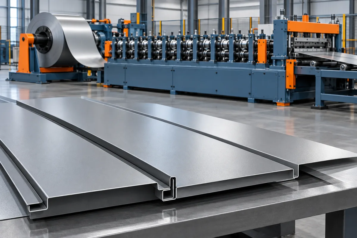
An architectural cladding roll forming machine produces repeatable metal profiles for facades where the visible face, joint pattern and consistency of the installed panel arrangement are important parts of the product. Its configuration must address both geometry and appearance: broad faces, narrow reveals, return legs and protected surfaces need to survive forming, cutting, handling and assembly.
The starting point is not a generic architectural style. It is a defined panel family with a manufacturable cross-section, specified material and agreed visual acceptance. Some facade components suit continuous roll forming; others need folding, cutting, joining or a combination of processes. Establish that boundary before choosing equipment.
Which architectural components suit roll forming?
Roll forming is worth evaluating for profiles with a repeating cross-section along their length. Examples can include flat-faced panels with formed edges, ribbed cladding and interlocking strip profiles. The edge details, face width and material must still be assessed individually; the fact that a part is long and metallic does not make it automatically suitable.
Facades can also contain folded trays, cassettes, tapered pieces, perforated areas and complex corners. End returns, varying widths and locally changing geometry may require operations beyond the main forming line. An equipment proposal should identify what is produced continuously and what remains a secondary fabrication task.
Three profile decisions that shape the line
Broad faces and defined reveals
Specify the exposed face width, return geometry and visible joint spacing together. The reveal depends on adjoining panels, so it should be judged on an assembly rather than inferred from one loose sheet. Appearance criteria need a stated viewing and support arrangement.
Ribbed or patterned faces
Identify whether the visual effect comes from the section shape, an embossed surface or the coating. Those are different production requirements. A pattern repeated through the roll tools is not interchangeable with a printed finish merely because photographs of the installed walls look similar.
Closed trays and special end conditions
If the component has returns across its ends or other nonconstant geometry, show how those features are made. Notching, folding or joining may follow the roll former. Review the complete part route rather than assuming the last forming stand delivers a finished facade cassette.
How is the architectural appearance translated into a drawing?
Begin with a facade concept, then identify the dimensions that control it: panel module, exposed face, joint width, alignment references and the way corners or openings interrupt the pattern. Translate those requirements into individual panel drawings and assembly details. This separates an aesthetic intention from the measurements used to approve tooling.
Mark functional datums and distinguish them from dimensions that are less important to fit. A return that locates a clip may require different attention from a concealed free edge. Avoid assigning arbitrary precision to every dimension while leaving the actual interface undefined.
- Show the complete section, including hidden returns and fixing features.
- Identify visible surfaces and where tooling contact is permissible.
- Provide the adjoining profile, clip or other locating component.
- Define cut ends and any secondary fabrication.
- State how the part and assembled panel group will be supported during inspection.
What happens through the production route?
- Material preparation: identify the production coil, finish, visible side and any protective film.
- Guided entry: feed the strip consistently while respecting the surface requirements.
- Progressive section development: form faces, shoulders and returns in the proposed sequence.
- Feature and end processing: make the specified holes, notches or cut ends in-line or by defined secondary operations.
- Supported discharge: move the panel without introducing distortion or contact damage.
- Assembly and appearance inspection: check the completed part against its functional and visual references.
The sequence should account for every operation needed to make a saleable component. If perforation or another feature is involved, establish its relationship to the bends and assembly datums before tooling is finalized. Adding it later can change the production route and acceptance requirements.
How should steel, aluminum and finishes be specified?
Use the exact material description relevant to the project: grade or alloy, thickness convention, coating, protective layers and surface direction where applicable. Two materials at the same nominal thickness can have different forming behavior. Trials should use production-intent material rather than a convenient substitute chosen only for easy forming.
For appearance-sensitive panels, record the finish on the approved sample and how it will be assessed. If material arrives with protective film, define its condition through forming, assembly inspection and packing. Damage can arise at guides or stacking supports as well as at the forming rolls, so the whole contact path belongs in the finish review.
A change in coating, alloy or backing should trigger a review of the relevant forming and appearance evidence. Keeping material identity with trial samples makes those decisions traceable without assuming that a previous successful run covers every later variation.
What does an appearance acceptance plan need?
Appearance should be discussed before production equipment is approved. Agree the panel length, supports, viewing conditions and reference material used for assessment. A short piece held flat on a bench and a long panel viewed under grazing light are not equivalent observations. Without a common method, buyer and supplier can reach different conclusions from the same material.
Separate scratches, coating damage, repeated contact marks and visible face waviness. Record when and where each occurs. Do not promise that a roll former eliminates every visual effect on every broad metal face; instead, establish the particular product's acceptance conditions and the evidence needed to demonstrate them.
Keep a physical approved sample or representative mockup, together with photographs taken under documented conditions. Photographs help communication, but they should not replace the agreed inspection method or conceal differences in support and lighting.
Why should a representative panel group be assembled?
A single profile cannot show how a reveal repeats across the facade. Assemble several panels with their intended attachments and inspect alignment, joint continuity and effective coverage. Include a representative termination or other interface if it is important to the product being supplied.
Use this assembly to distinguish part geometry from support or installation effects. Record whether panels engage normally, whether the reveal is consistent and whether local modification was needed. A mockup that requires unplanned forcing is not evidence of repeatable manufacture simply because its final photograph looks satisfactory.
The agreed assembly checks should remain connected to the component drawings. This makes them usable during repeat production and tooling changes, not merely as a one-time display exercise.
How are profile variants and changeovers handled?
Create a matrix of face widths, returns, joint designs, materials and lengths. Identify variants that share a joint and those that change the actual mating geometry. A width adjustment within a reviewed family is different from introducing a new fixing system or end condition.
Ask the proposed supplier to map each variant to the necessary rolls, guides, feature tools and cutting components. Include downstream fixtures where the finished component needs further fabrication. The matrix reveals whether the project suits dedicated equipment, changeable tooling or a mixed manufacturing route.
Assess the complete first-good-part changeover. A quick tooling swap has limited value if appearance or joint fit takes extensive recovery afterward. Record setup material, inspection work and the ability to return to an earlier accepted profile.
What determines practical output and packing requirements?
Architectural components may be supplied in small color batches, varied lengths or installation sequences. Accepted output should therefore be measured against a representative order rather than an uninterrupted run of one easy profile. Identification, separation and packing can be essential parts of completing that order.
Review how finished faces are protected from adjacent panels, straps, support surfaces and movement during handling. A successful forming trial followed by damaged packing does not deliver a usable result. Include package format and order identification in the process review, especially where many similar panels serve different positions on a facade.
How should quotations and trial scope be compared?
Compare the same finished-part family and appearance requirement in every proposal. Separate main forming equipment, profile tools, feature-making operations, secondary fabrication, handling and commissioning responsibilities. A line producing an unfinished strip should not be priced as equivalent to a route supplying completed architectural components.
The acceptance plan should connect the agreed drawing, material and assembly method. It can include the following checks without turning the equipment purchase into an undefined promise about every possible facade:
- Measure the functional profile and end dimensions after the specified operations.
- Inspect the exposed face using the documented appearance method.
- Assemble a representative panel group with the intended attachment components.
- Demonstrate normal discharge, protection and packing.
- Run an agreed variant change and inspect recovered output.
- Record exclusions and any additional project-level testing responsibilities.
Frequently asked questions
Can the machine make every facade panel shape?
No single general description establishes that scope. Constant sections are the starting point for a roll-forming review; trays, special ends or changing geometry may need other processes. Supply complete drawings and ask for a part-by-part route rather than a blanket architectural-cladding claim.
Is a perfectly flat appearance guaranteed by more forming stations?
No. Appearance depends on the defined section, material, process, handling and inspection conditions. Station count alone is not an appearance specification. Compare the relevant trials and agreed acceptance result, not an isolated machine number.
Can a visible reveal be changed independently of panel width?
It depends on the joint design and the proposed tools. Reveal and coverage are assembly dimensions, so changing one may affect the mating edges or installation interface. Request the actual variant drawing and tooling review rather than assuming independent adjustment.
Does the line supply clips, corner trims and closures?
Only if their manufacture or supply is included in the scope. These parts may require separate tooling or fabrication. Make an accessory schedule and assign responsibility for each item so the complete panel system can be assembled during approval.
Should inspection be performed before or after protective film removal?
Define that in the product's acceptance method. Film can affect what is visible during inspection, while removing it may change handling requirements. Agree how the finished surface is evaluated and how approved panels are protected afterward.
What should accompany the first enquiry?
Provide the section and assembly drawings, intended material and finish, representative lengths, variants and accessory interfaces. Add the appearance reference and order pattern. These inputs make tooling, secondary operations and handling requirements substantially clearer.
Turn the facade design into a repeatable production brief
The strongest specification links architectural intent to measurable section geometry, material identity, assembly checks and appearance conditions. Use that connection to choose a practical process rather than asking a general machine label to solve an undefined facade. Related wall-panel and concealed-fix pages can help narrow the component family before the detailed tooling discussion.

Continue your research
- Wall Cladding Roll Forming Machines
- Wall Panel Roll Forming Machine
- Metal Siding Roll Forming Machine
- Box Profile Wall Panel Roll Forming Machine
- Corrugated Wall Cladding Roll Forming Machine
- Trapezoidal Wall Cladding Roll Forming Machine
- How Wall cladding roll forming machine Works
- How To Choose a Wall cladding roll forming machine
- Wall cladding roll forming machine Price: What Affects the Cost?
Configuration & specification inputs
Match the configuration to your section drawing, material and production requirements.
| Parameter | Requirement / confirmation needed |
|---|---|
| Profile geometry | Exposed face, joint reveal, hidden returns, functional datums and all secondary end details. |
| Material | Production-intent grade or alloy, coating, surface direction where applicable and protective film. |
| Thickness & grade | Material combinations reviewed against the section, bend development and agreed appearance conditions. |
| Process route | Material preparation, protected entry, progressive forming, specified secondary work, discharge and assembly inspection. |
| Cutting | Required lengths and end geometry coordinated with notching, folding or joining where specified. |
| Output | Accepted architectural components after required fabrication, inspection, identification and protection. |
| Electrical supply | Site electrical supply and auxiliary utilities for the agreed complete manufacturing route. |
| Acceptance | Functional geometry, documented appearance conditions, assembled reveals and joints, packing and changeover recovery. |