
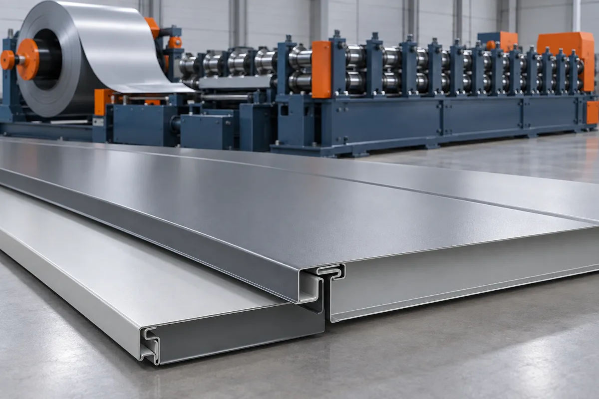
A concealed-fix wall panel roll forming machine produces cladding profiles whose attachment is hidden by the panel joint or adjacent panel. The clean facade appearance comes from a functional edge design: the formed returns must engage correctly, provide access during installation and work with the specified fastener flange or separate clip. The central face and the hidden joint therefore need to be treated as one product.
Compared with selecting a general wall-sheet former, the key questions move toward joint fit, clip compatibility, appearance and repeatable assembly. A profile that looks correct from the front can still fail to install if its hidden return or fixing clearance is wrong.
What makes a wall panel concealed-fix?
The fixing is covered in the finished installation rather than exposed across the principal panel face. Different systems achieve this in different ways. One design may attach through a flange that the next panel covers; another may engage separate clips. These arrangements must not be treated as interchangeable merely because both produce a facade without visible face fasteners.
The panel drawing should show both adjoining edges, the fixing or clip, the supporting interface and the sequence used to connect panels. It should also identify the visible reveal or joint spacing. The roll former's job is to reproduce that geometry consistently along each length while preserving the appearance of the exposed face.
Clip-fastened and covered-flange designs: what changes?
A separate clip interface
The panel contains a formed feature that engages the chosen clip. Important dimensions can include the internal opening, return depth and contact surfaces, but the exact requirements come from the system drawing. Provide production-intent clips during tooling review. A similar-looking clip from another source is not automatically compatible.
A fixing flange covered by the next panel
The profile includes an area through which it is attached before the adjacent panel hides that fixing. The brief needs to identify flange width, any specified holes or slots and installation access. Confirm whether feature-making is part of the proposed line or a separate operation.
What both arrangements require
Approve the joint as an assembly, not as two unrelated edge measurements. It must match the intended installation method without unplanned forcing or local modification. Any fixed or movement-accommodating behavior must be defined by the wall-system design rather than inferred from the words concealed fixing.
Where does a concealed-fix production line fit?
This route is worth evaluating when the product range emphasizes uninterrupted visible faces and deliberately designed panel joints. The manufacturing brief may prioritize a broad architectural face, a repeated reveal or a particular rib pattern. Each choice changes what needs attention in tooling, handling and acceptance.
Consider how the panels will be sold and installed. A stable system using one joint and a few face widths creates a different tooling requirement from a catalogue of unrelated proprietary joints. Keep the product family narrow enough to describe clearly before asking for universal changeover capability. A common application does not make different concealed-fix profiles one interchangeable machine setup.
How is the hidden joint formed?
The strip passes through successive stages that develop the face, shoulders and edge returns. Tight or re-entrant details require attention to how tools contact the material and remain accessible as the section closes. The final edge is the result of that sequence, the selected material and the agreed process settings.
- Prepare and guide the strip: establish coil orientation, input width and the surfaces that require protection.
- Create specified fixing features: integrate holes or slots where required, with a defined relationship to panel length and formed datums.
- Develop the section: progressively form the face geometry and the complementary joint edges.
- Complete and inspect the returns: check the dimensions and contact areas that govern clip or adjacent-panel engagement.
- Cut and support the panel: preserve the hidden edge geometry through cutoff and discharge.
- Assemble representative panels: use the specified fixings or clips and the intended installation sequence.
Ask for the actual proposed layout. The position of a feature-making or cutting operation is an engineering choice, not something that can be established from the product name alone.
Which specification inputs matter most?
Begin with a controlled cross-section rather than a facade rendering. The drawing needs to explain what is visible and what happens behind the face. Where another component controls fit, include that component's drawing and physical sample in the approval package.
- Panel face and reveal: define the exposed width, any ribs and the appearance of the assembled joint.
- Hidden returns: identify depths, openings, bend radii and the relevant contact surfaces.
- Attachment: specify the clip or covered flange, fastener access and required holes or slots.
- Effective cover: state how coverage is measured after the panels engage.
- Material: record grade or alloy, base-metal thickness, coating and any protective film.
- Length and orientation: list production lengths and the intended installation direction.
- Finish acceptance: agree the viewing and support conditions used to assess the visible face.
These inputs define a configuration envelope. They also separate a genuine adjustment within one profile family from a new joint geometry that needs additional engineering or tools.
How do material and coating affect joint fit?
The return geometry is formed in the chosen material, so material properties and surface condition cannot be separated from the tooling discussion. A different steel grade or aluminum alloy may behave differently during bending. Equal thickness by itself does not establish equal springback or the same result at a tight return.
Use the actual coated material for joint trials and identify how thickness is specified. Evaluate coating condition at the bends and the contact areas used during engagement. If protective film is part of the production process, define when it is present and removed during inspection. An approved bare-metal sample is not a complete finish or assembly reference for a coated architectural panel.
Can one line make different widths and joint styles?
Different widths using one joint concept and different joint concepts at the same width are separate requirements. A supplier may propose adjustments for some dimensions, replacement rolls or cassettes for others, and different punch or cutoff components where needed. Ask for a configuration matrix listing every target profile and the work required to move between them.
Measure changeover from the last accepted panel of one order to the first accepted panel of the next. Include guides, tooling, feature programs, cutting support and inspection. A short stand-adjustment demonstration does not show the complete recovery time if an operator still needs to change tools or correct the first batch.
How should joint fit and face appearance be checked?
Use separate but connected checks. Joint inspection confirms that panels and attachments engage as designed. Appearance inspection assesses the exposed face under agreed conditions. A satisfactory joint does not excuse a marked face, while an attractive panel does not prove that the hidden connection works.
For assembly, use several panels with the intended clips or fixing arrangement on a representative support. Inspect continuity of the reveal, effective coverage and the condition of returns after normal handling. Record unexpected resistance, looseness or the need for local alteration instead of concealing those observations in the assembly demonstration.
For appearance, document the material, length, support and lighting. Broad faces should not be judged from unrelated photographs taken under different conditions. Retain agreed samples and inspect before and after discharge so forming marks can be distinguished from damage caused by stacking or handling.
Which production problems deserve their own investigation?
A joint that is too tight or will not engage
Check the intended clip or mating panel first, then compare the hidden return with the approved drawing. Record the actual material and the stage at which the problem appears. Do not assume every engagement issue can be solved by opening the visible edge.
An uneven reveal across assembled panels
Examine the section and assembly references together, including cover width, straightness and the support arrangement. A panel should not be forced into place merely to make the reveal appear correct during approval. Distinguish part geometry from installation alignment.
Marks near the lock or on the broad face
Trace contact through forming, cutting and takeoff. Keep scratches, coating damage and visible waviness as separate observations. Physical inspection and machine adjustments should follow the equipment supplier's procedures, with qualified personnel and the required isolation.
What affects the quotation and accepted production rate?
The complexity of the hidden joint, number of profile variants, feature-making scope and surface-protection arrangements all affect the package. Include the matching cutoff support, discharge equipment and required change parts when comparing quotations. Clips, accessory manufacture and building-system validation should have clearly assigned responsibilities rather than disappearing inside a vague complete-line description.
For output, use accepted panels produced during a stated trial with the actual material and length mix. Joint inspection, color changes and separated handling may constrain the complete route. A high nominal strip speed has little value if the resulting panels need rework or their finish is damaged before packing.
What belongs in a factory acceptance trial?
- Approve the drawings, material identification, clip or fixing references and measurement methods.
- Produce the agreed section and representative lengths using the specified material.
- Measure hidden returns, fixing features, face geometry and finished ends after cutting.
- Assemble several panels using the intended attachment sequence and assess the resulting joint.
- Inspect appearance before and after normal takeoff and packing.
- Demonstrate agreed configuration changes and inspect the recovered production.
- Record accepted output, rejected pieces and any unresolved deviations.
Define manufacturing acceptance separately from the wall assembly's project-specific performance requirements. This keeps a successful machine trial from being confused with a conclusion about an entire facade.
Frequently asked questions
Does every concealed-fix panel use a separate clip?
No. Some designs use a fixing flange covered by the adjoining panel. Others engage separate clips. Specify the actual joint and fastening arrangement; this determines the edge tools, access and any required feature-making operations.
Can clips from another panel system be used?
Do not assume compatibility from appearance or nominal size. Compare the complete interface with the approved system design and use the intended components during trials. Substitution needs the relevant design review, not simply a successful improvised fit.
Can the same panel be installed vertically and horizontally?
Use the installation directions approved for that panel system. Orientation can affect joint, drainage and supporting details even when the roll-formed cross-section looks unchanged. The equipment specification should follow the intended product, not establish installation suitability by itself.
Does a hidden fixing automatically make the wall weatherproof?
No. Weather performance involves the defined wall assembly, joints, openings, interfaces and installation. Concealing the fastener describes an attachment arrangement. It does not replace the design and verification needed for the complete facade.
Can a flat-faced panel replace a ribbed version on the same line?
That depends on how the proposed tooling creates the face and edges. Ask which components change and how the resulting panel will be supported and inspected. Sharing a hidden joint does not necessarily make different face geometries a simple control adjustment.
What information makes a quotation useful?
Provide the complete section and joint drawing, attachment samples, material specification, lengths and required variants. Add appearance criteria and a representative order mix. These inputs make it possible to compare tools, changeover, handling and acceptance on the same basis.
Start with the joint, then specify the production line
The most useful starting package is a panel drawing plus its mating components, not a photograph of a finished wall alone. Define engagement, appearance and production requirements together. The resulting brief connects the concealed-fix product customers will install to the equipment and checks needed to manufacture it consistently.

Continue your research
- Wall Cladding Roll Forming Machines
- Wall Panel Roll Forming Machine
- Metal Siding Roll Forming Machine
- Box Profile Wall Panel Roll Forming Machine
- Corrugated Wall Cladding Roll Forming Machine
- Trapezoidal Wall Cladding Roll Forming Machine
- How Wall cladding roll forming machine Works
- How To Choose a Wall cladding roll forming machine
- Wall cladding roll forming machine Price: What Affects the Cost?
Configuration & specification inputs
Match the configuration to your section drawing, material and production requirements.
| Parameter | Requirement / confirmation needed |
|---|---|
| Profile geometry | Visible face and reveal, effective cover, complementary hidden returns, fixing access and mating joint surfaces. |
| Material | Specified coated steel or aluminum with production-intent attachment samples and finish requirements. |
| Thickness & grade | Defined grade or alloy and base-metal thickness, reviewed against the tight returns and required joint fit. |
| Process route | Protected strip entry, specified fixing features, progressive face and return forming, supported cutoff and assembly inspection. |
| Cutting | Required lengths and end quality without unacceptable deformation of the concealed joint or fixing flange. |
| Output | Accepted panels during a defined run with the actual length mix, joint inspection and separated handling. |
| Electrical supply | Site voltage, frequency and phase; confirm auxiliary requirements for the agreed equipment configuration. |
| Acceptance | Hidden-return geometry, specified attachment engagement, assembled reveal and coverage, face appearance and changeover recovery. |