
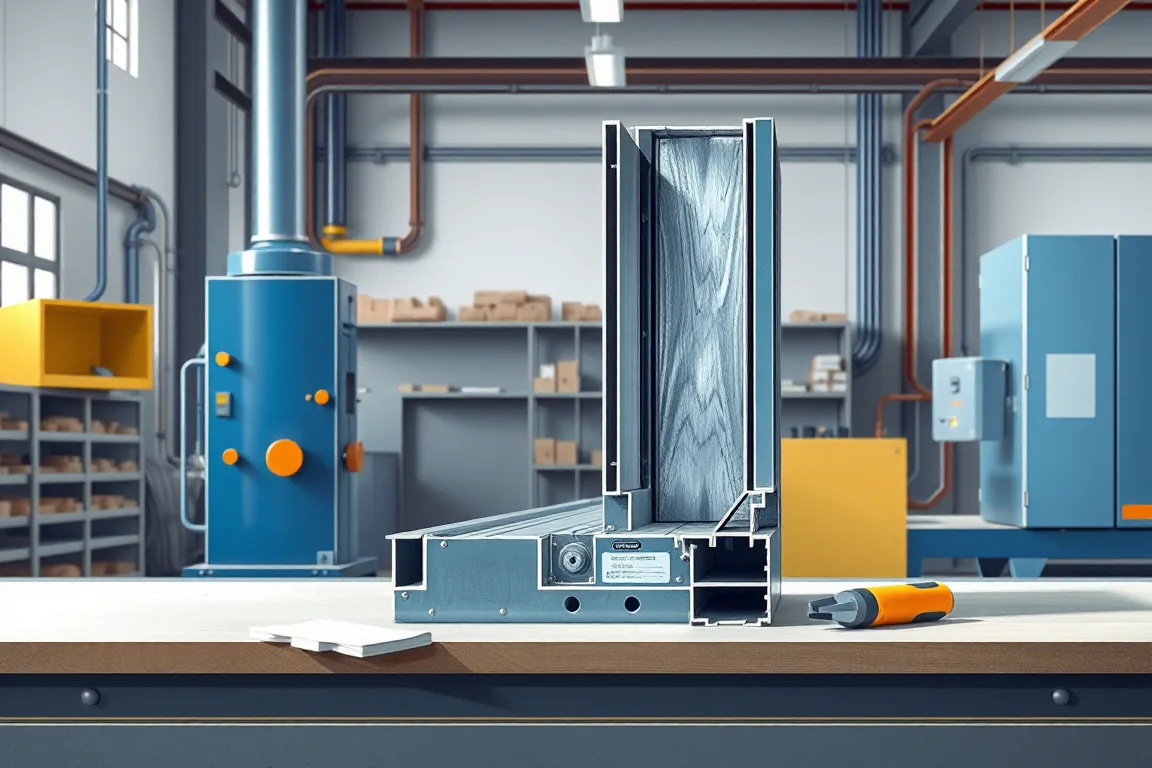
Choosing a door frame roll forming machine begins with the finished frame, not the machine. A door frame is not only a folded section; it is a system that must accept a door leaf or glazing panel, hinges and latch hardware, seals, and a corner joint. The machine is one part of a manufacturing route that may include punching or notching, forming, cutting to length, and corner assembly. The right selection is the route that can produce your specific section and finished frame repeatedly, within the tolerances your assembly and installation require.
Start With the Finished Frame, Not the Machine
Before comparing any equipment, define the frame as a manufactured part. The profile drawing should show the rebate, jamb returns, any hinge or latch feature, seal grooves or lands, and the material thickness and grade. The assembly drawing should show how corners are joined — welded, mechanically crimped, corner-cleated, or another method — and whether the frame is delivered knocked-down or assembled. These two documents determine which operations the machine must perform and which are better handled separately.
If a fire-rated or otherwise certified assembly is required, the machine does not provide that rating. Rating depends on the complete tested and approved door system, including installation. The machine's role is to produce geometry that matches the approved design. Confirm that your section and assembly details fall within the scope of the intended certification before ordering tooling.
Map the Production Sequence and Its Interfaces
A typical route runs from blank or coil preparation, through feature punching or notching, into forming, then cutoff, and finally corner assembly. Each step has an interface where quality can be gained or lost:
- Coil or blank preparation: material grade, thickness, edge condition, and flatness influence forming consistency.
- Feature punching or notching: hinge and latch preparations may be done before or after forming. Before forming, the flat strip is easy to locate and tool; after forming, the feature must be reached in a shaped section.
- Forming: the roll set creates the continuous section. Narrow returns and multiple bends require attention to tool access and to how the strip is supported between stations.
- Cutoff: the cut must suit the formed section. Confirm whether it is a shear, saw, or another method, what end quality is acceptable, and whether a secondary operation is needed.
- Corner assembly: joining is often a separate operation. Confirm whether corner preparation is done in the line or offline, and how it aligns with the frame drawing.
The interfaces matter more than any single station. For example, a punching operation placed after forming may require the section to be opened or the punch to reach inside a return. A cutoff placed after forming must cope with a profile that may not sit flat. If corner preparation is offline, the machine only needs to deliver correct end geometry; if it is inline, the line must produce both the section and the corner feature.
Match Forming Capability to the Section Family
Roll forming is a continuous process: a strip of material is progressively bent through a series of rolls until it matches the target section. Forming design depends on the number and sequence of bends, the direction of each bend, the material grade and thickness, and the space available for tooling. Sections with deep returns, tight bend radii, or features close to one another can be formed, but they require more stations, careful roll positioning, and sometimes a different bend order.
When evaluating a machine, ask how the proposed roll set handles your specific section — not a similar one. A section family with many variations may be better served by a machine that accepts interchangeable roll sets or adjustable stations; a single high-volume profile may be better served by a dedicated roll set. The trade-off is changeover time, tooling cost, and risk of setup error against the simplicity and repeatability of a dedicated line.
Material and Thickness Decisions You Must Resolve
Material and thickness drive tooling design, forming forces, and springback. The buyer should specify the base-metal thickness and grade, and request supplier verification of the operating range. Stainless steel and other alloys behave differently from mild steel and typically need separate tooling validation; a roll set proven on one material is not automatically suitable for another.
Thickness variation within a coil or between batches affects the formed section. If your supply includes more than one thickness or grade, decide whether the machine must handle that range or whether you will dedicate tooling to each. A machine that handles a wide range may require more adjustment and more operator skill; a narrower range can be more repeatable.
Cutting, End Quality, and Secondary Operations
Cutoff is where the formed section becomes a part. The cutting method must suit the profile: a shear may deform thin or open sections, while a saw or other method may be needed for heavier or more complex shapes. Confirm what cutoff is supported by the section, what cut lengths are required, what end quality is acceptable, and whether any secondary operation — deburring, end forming, or corner preparation — is necessary.
Cut length accuracy and squareness affect the assembled frame. If the frame is assembled from cut lengths, small errors can accumulate across the corner joint. Agree on how cut lengths will be measured and what tolerance is acceptable before committing to tooling.
Corner Assembly and Hardware: Where the Frame Becomes a Product
The finished frame must accept the intended door or glazing system, hardware, and seals. Hinge preparation, latch features, and corner joining may be separate operations from roll forming. This separation is normal, but it must be planned. Ask whether corner preparation is done in the line or offline, and how the frame is held during assembly.
A practical acceptance test uses the actual hardware and a representative corner joint. Inspect rebates and seal lands for geometry and surface condition, then assemble the corner and measure the finished frame after assembly as well as the unjoined section. The unjoined section shows what the forming and cutting operations produced; the assembled frame shows whether the route as a whole meets the drawing.
Output: Define Accepted Parts, Not Just Machine Speed
Output should be defined as accepted parts per shift with the actual profile and material. No verified model rating applies to your combination of section, material, and operations. Factors that reduce accepted output include setup and changeover, punching or notching time, cutoff cycle, corner assembly, inspection, and rework. When comparing proposals, ask what assumptions are built into any output figure: profile, material, thickness, feature content, and whether corner assembly is included.
A machine that forms quickly but requires long changeovers may suit high-volume single-profile production and be a poor fit for a mix of frames. Conversely, a flexible machine may have a lower peak rate but higher effective output across a varied order book. The right measure is accepted parts per shift for your product mix, not a single speed number.
Power, Controls, and Site Interfaces
State your voltage, frequency, and phase before requesting a proposal. Installed power requires a confirmed equipment schedule that includes every motor, heater, and control on the line. Controls should be matched to the operators and maintenance resources available: a simple, well-documented control system may be more productive than a complex one that is underused. Consider how programs, recipes, and changeover settings are managed, and how the machine interfaces with upstream coil handling and downstream assembly.
Why a Meaningful Demonstration Matters
A demonstration should use your section and material, not a convenient sample. Watch the sequence from strip to cut part, then inspect the formed features: rebates, seal lands, hinge and latch preparations, and cut ends. Measure both the unjoined section and a representative assembled corner. If a demonstration cannot use your material, ask what differs and how that difference is accounted for in the proposal.
Separate a confirmed capability from a proposed future option. A machine that has produced a similar section is not the same as one that has produced your section. Ask which elements are proven, which are adaptations, and which are new. New tooling is not a disqualification, but it should be treated as a development risk with an agreed acceptance process.
How to Compare Alternatives
Compare routes and machines on the same drawing revision, material envelope, and finished-part scope. A useful comparison sets three columns: required, included, and excluded. Required is what your product needs; included is what the proposal covers; excluded is what you must supply or add. Typical alternatives include:
- A dedicated line for one profile family versus a flexible line with interchangeable or adjustable tooling.
- Inline punching and corner preparation versus offline secondary operations.
- A single supplier for forming, punching, and cutoff versus separate suppliers for each step.
- A new machine versus a reconditioned or repurposed line; the latter may need tooling validation for your section.
If production depends on equipment outside the quote — a press, a welder, a corner assembler — include that equipment in the comparison. A lower machine price with a large offline workload may not be the lower route cost.
Cost: What a Quote Should Cover
Cost is not a single number. A meaningful quote separates the machine, tooling, installation, commissioning, training, spares, and any offline equipment. It should also state what is excluded and what assumptions are made about material, profile, and output. To compare routes, estimate cost per accepted part: include material yield, labor for each operation, tooling life and replacement, changeover time, and expected rework. This accepted-output cost is more useful than a machine price alone, because it reflects the whole route.
Do not accept a price comparison that uses different scopes. One proposal may include corner assembly equipment; another may not. One may include a full roll set for your section; another may assume a generic set. Align the scopes before comparing.
Acceptance Measurements to Agree Before Tooling
Agree acceptance measurements before committing to tooling. A practical set includes:
- Section dimensions at the rebate, returns, and seal lands.
- Feature positions for hinges and latch preparation.
- Cut length and end squareness.
- Corner joint fit and finished frame dimensions after assembly.
- Surface condition relevant to finishing or sealing.
Record how each measurement is taken, on which sample, and under what conditions. Acceptance should use the actual hardware and a representative corner joint, not only a formed section.
FAQ
Can one machine make different door frame profiles?
It can if the machine is designed for changeable or adjustable tooling and the profiles share a compatible material and forming approach. The trade-off is changeover time, setup skill, and the risk of error between runs. A dedicated roll set for one profile family usually gives more repeatable output; a flexible arrangement suits a varied order book. Confirm changeover with a demonstration using your intended product mix.
Should hinge and latch features be punched before or after forming?
Punching before forming is often easier because the strip is flat and the tool can be positioned simply. Punching after forming can avoid distortion of the finished section but requires access into a shaped profile. The choice depends on feature location, section geometry, and whether the feature must be formed after bending to maintain its shape. Confirm which operation the proposed line performs and how the feature is located.
How do I define output for a door frame roll forming machine?
Define output as accepted finished frames or cut lengths per shift for your actual profile, material, and operations. Include setup, changeover, punching, cutoff, corner assembly, inspection, and rework in the calculation. A machine's forming speed alone does not determine accepted output. Ask what assumptions are behind any proposed output figure and whether they match your product mix.
What material information must I provide before ordering tooling?
Provide grade, base-metal thickness, and any coating or finish. State whether the material is mild steel, stainless, or another alloy, because different materials need separate tooling validation. Also state thickness variation across your supply. A roll set proven on one material is not automatically suitable for another, and tooling design depends on these inputs.
How should corner assembly be handled in the machine selection?
Treat corner assembly as part of the route, whether inline or offline. If it is offline, the machine must deliver correct end geometry and cut length for the corner method. If it is inline, the line must produce the corner feature and the frame must be held during joining. In both cases, test with a representative corner joint using the actual hardware, and measure the finished frame after assembly.
What should I inspect during a demonstration?
Inspect the formed section for rebates, seal lands, and feature positions, and check cut ends for length and squareness. Then assemble a representative corner with actual hardware and measure the finished frame. Observe the sequence from strip to cut part, including punching and cutoff. If your material is not used, ask what differs and how the proposal accounts for that difference.
Does a fire-door frame machine certify a fire-rated assembly?
No. A machine does not certify a fire-rated assembly. Rating depends on the complete tested and approved door system, including installation. The machine's role is to produce geometry that matches the approved design. Confirm that your section and assembly details fall within the scope of the intended certification before ordering tooling.
Decision Checklist
- Define the finished frame: section drawing, assembly drawing, hardware, seals, and corner method.
- State material grade, thickness, and any expected variation.
- Map the sequence and decide which operations are inline and which are offline.
- Compare the same drawing revision, material envelope, and finished-part scope across proposals.
- Request a demonstration or a clear statement of what is proven and what is new.
- Agree acceptance measurements and the measurement method before tooling.
- Compare cost per accepted part, including offline operations, labor, tooling life, and rework.
- Confirm site interfaces: power, controls, changeover, and upstream and downstream equipment.
Making the decision against a fixed drawing and a defined route keeps the comparison honest. The machine is only one element; the finished, assembled, accepted frame is the real measure of whether the choice was right.
Continue your research
- Door & Window Profile Roll Forming Machines
- Steel Door Frame Roll Forming Machine
- Window Frame Roll Forming Machine
- Hollow Metal Door Frame Roll Forming Machine
- Garage Door Track Roll Forming Machine
- Door Reinforcement Channel Roll Forming Machine
- How Door frame roll forming machine Works
- Door frame roll forming machine Price: What Affects the Cost?
- Materials and Thickness for Door frame roll forming machine