
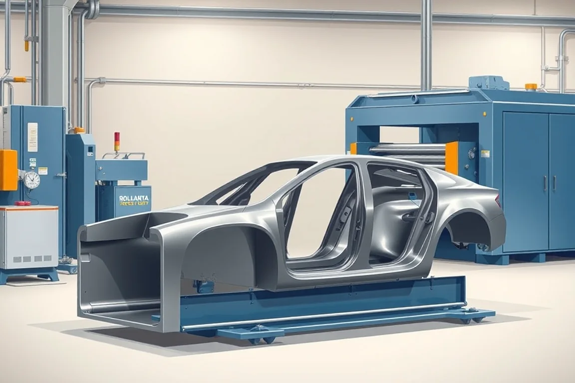
What the finished structural profile actually is
A car body structural profile is not simply a bent strip. It is a controlled part defined by a drawing that sets section geometry, datums, hole patterns, joining flanges and assembly interfaces. The profile may be an open section, a closed or semi-closed section, or a shape with local features that locate it against other body components. Its function determines which features matter most: a flange that welds to a panel must sit flat and repeatably, a pierced hole that receives a fastener must align with its mating part, and a datum surface used for checking must be stable enough to measure against.
The finished profile therefore has several categories of requirement. Geometric requirements include bend angles, web and flange widths, corner radii and overall straightness or sweep. Interface requirements include flange orientation, hole position, notch location and any edge condition needed for joining. Material requirements include grade, coating, thickness and allowable variation. The forming process must satisfy all of these together, because correcting one feature by adjusting a pass can move another.
Why the datum scheme and interfaces drive the tooling
Datums are the reference features from which dimensions and hole positions are measured. If the drawing uses a web surface as a primary datum and a flange edge as a secondary datum, the forming and cutting stations must preserve those relationships through every operation. A seemingly small change in springback at a bend can shift a flange enough to move an assembly interface out of position, even when the overall section still looks correct.
Joining flanges and assembly interfaces are where a structural profile stops being a generic roll-formed shape and becomes a car body part. A flange intended for spot welding or adhesive bonding needs consistent angle and flatness. A pierced feature intended for a bolt or clip needs consistent position relative to the datum. When these interfaces are not identified early, a production line can produce parts that fit a gauge but not the vehicle.
Reading the drawing before specifying a machine
The drawing is the primary specification. Before evaluating any machine, confirm the section geometry, the datum scheme, the holes and notches, the joining flanges and the assembly interfaces. Then identify the material: grade, strength, coating and allowable thickness variation. High-strength steels and some coated products behave differently from mild steel in terms of bend radii, springback and pass development, so the material must be treated as part of the forming problem rather than an interchangeable input.
A useful review separates what the drawing requires from what the machine can influence. Forming affects angles, radii, straightness and springback compensation. Cutting affects end quality, burr condition and cut-length consistency. Feature operations affect hole position, notch geometry and edge quality. Joining, if performed in line, affects the final interface. Each of these should be traceable to a drawing requirement and a measurement method.
The production route from coil to verified part
A typical route for a car body structural profile is traceable coil feed, precision forming, feature and cut operations, joining where required, and dimensional verification. Coil feed should be traceable so that material lot, coating and thickness can be connected to the finished part. Precision forming develops the section progressively through a series of passes, with each pass contributing a controlled amount of bend. Feature and cut operations may include piercing, notching, slotting and cutoff, either integrated into the forming line or performed separately.
Joining is often a separate operation because welding, adhesive bonding or mechanical fastening may require fixtures and access that the forming line does not provide. Dimensional verification should follow the agreed acceptance plan, using the datums and measurement method defined for the part. The route should be reviewed as a whole, because a change in one operation can move a feature measured in another.
Tooling alternatives and what they change
Tooling alternatives include the number and arrangement of forming passes, the use of adjustable or dedicated stations, the method of springback compensation, and the choice between in-line and offline feature operations. A dedicated tool set is built around one profile and one material condition. An adjustable arrangement may allow some variation in flange width or bend angle, but the range must be verified for the actual section rather than assumed from a general capability.
Piercing and notching can be integrated into the forming line or performed on a separate press. Integrated operations reduce handling and can improve feature-to-datum consistency, but they constrain the line layout and may increase changeover time. Offline operations can use more accessible tooling and may be easier to maintain, but they add a handling step and require their own position control. Cutoff tooling must be matched to the profile so that the cut is supported and the end condition meets the drawing. The choice among these alternatives should be made against the accepted output definition, not against a generic claim of flexibility.
Changeover, setup and scrap discipline
Changeover is the sequence of steps needed to move from one profile or material to another. It includes tool changes, roll adjustments, sensor and program changes, and the first-off inspection that confirms the line is producing to the drawing. Setup scrap is the material consumed before the line reaches stable production. Both changeover time and setup scrap are part of the production reality and should be recorded rather than estimated from a no-load speed.
A practical changeover plan lists each step in order, identifies who performs it, and states how the first-off part is checked before release. The plan should connect machine settings to observable part requirements, so that an operator can tell whether a flange angle or a hole position is correct without waiting for a full dimensional report. Recording changeover steps, setup scrap, piercing time and unloading time gives a more honest picture of output than an isolated machine speed.
Cutoff and end quality
Cutoff requirements should be confirmed against the profile. The cut must be supported so that the section does not collapse or distort, and the cut length must be consistent. End quality includes burr condition, edge squareness and any deformation near the cut. If the drawing calls for a secondary operation such as deburring, chamfering or end forming, that operation should be listed in the scope rather than assumed to be part of the cutoff station.
Cut length is often tied to a downstream assembly or handling requirement. A part that is slightly long or short may still form correctly but fail at the next station. For that reason, cut-length verification should use the same datum and measurement method as the rest of the acceptance plan.
Inspection and accepted output
Accepted output is defined by the actual profile and material, not by a general machine rating. Before tooling approval, agree on the inspection features, the measurement equipment, the identification method and the relevant process records. The inspection plan should state which datums are used, how the part is supported during measurement, and what variation is acceptable. First-off pieces and a representative steady-production sample should be inspected with the agreed gauges.
The production discussion should connect machine settings to observable part requirements. If a flange angle is measured with a gauge, the gauge should reference the same datum as the drawing. If a hole position is checked, the check should reflect the assembly interface it serves. This makes the inspection meaningful rather than a pass or fail against an unrelated dimension.
Separating machine scope from part validation
The production hardware and the part-validation responsibilities are separate scope items. Production hardware includes the coil feed, forming stations, feature and cut operations, joining equipment and handling. Part validation includes forming simulation or trial evidence, gauge design, first-off and steady-production inspection, and any crash or durability qualification required by the vehicle program. A general roll-forming capability does not demonstrate compliance with an OEM's part or crash requirements, so the validation plan should be agreed independently of the machine purchase.
When reviewing a quotation, compare the written equipment scope with all secondary operations needed for a finished part. Tool development, trials, gauges, joining and qualification support can be substantial scope items. Separating them prevents the assumption that a forming line alone delivers a validated structural component.
How this differs from adjacent automotive profiles
Automotive bumper beams, door beams and truck side beams are related but distinct. Bumper beams often involve curved or swept sections with specific energy-absorption requirements. Door beams may prioritize intrusion resistance and a particular mounting interface. Truck side beams are typically larger and may have different straightness and hole patterns. A car body structural profile may share roll-forming principles with these parts, but its drawing, material, interfaces and validation plan are specific to the vehicle body application. Treating them as interchangeable can lead to tooling and inspection decisions that do not fit the part.
Practical checklist before approving a production line
- Confirm the drawing: section geometry, datums, holes, notches, joining flanges and assembly interfaces.
- State the material: grade, strength, coating and allowable thickness variation.
- Review forming simulation or trial evidence for the actual section and material.
- Confirm access to critical features and whether piercing, joining or sweeping is integrated or separate.
- Agree the inspection features, measurement method and acceptance criteria before tooling approval.
- Record changeover steps, setup scrap, piercing time and unloading time.
- Run the agreed material and profile, not an easier demonstration substitute.
- Inspect first-off pieces and a representative steady-production sample with the agreed gauges.
- Compare the written equipment scope with all secondary operations needed for a finished part.
- Separate production hardware from part-validation responsibilities.
Frequently asked questions
What defines a car body structural profile?
It is defined by a controlled part drawing that specifies section geometry, datums, holes, joining flanges and assembly interfaces, together with the material grade, coating and thickness. The drawing, not the machine, is the primary specification. The producing line must satisfy those requirements simultaneously, because adjusting one feature can move another.
Why does material grade affect the forming process?
Higher-strength steels and some coated products can require different bend radii, pass development and springback compensation compared with mild steel. Springback changes the final angle after the rolls release the strip, so the tooling and pass schedule must be developed for the actual material condition rather than a generic substitute.
Should piercing and cutoff be integrated into the forming line?
Integrated operations can reduce handling and improve feature-to-datum consistency, but they constrain line layout and may increase changeover time. Offline operations can use more accessible tooling but add a handling step and require their own position control. The choice depends on the accepted output definition for the specific part.
How should output be defined for this equipment?
Accepted output should be defined per shift using the actual profile and material, with the inspection and traceability process included in the cycle-time calculation. Setup scrap, changeover and unloading time matter more than an isolated no-load speed, so the output definition should reflect the real production sequence.
What should be inspected before releasing a production run?
The first-off part and a representative steady-production sample should be inspected using the agreed datums, measurement equipment and acceptance criteria. The inspection should connect machine settings to observable part requirements, and the records should identify the material lot and process conditions.
What is the difference between production hardware and part validation?
Production hardware includes the coil feed, forming stations, feature and cut operations, joining equipment and handling. Part validation includes forming simulation or trial evidence, gauge design, inspection and any crash or durability qualification. A general roll-forming capability does not by itself demonstrate compliance with an OEM's part or crash requirements.

Continue your research
- Automotive Roll Forming Machines
- Automotive Bumper Beam Roll Forming Machine
- Automotive Door Beam Roll Forming Machine
- Automotive Seat Rail Roll Forming Machine
- Automotive Window Guide Channel Roll Forming Machine
- Heavy Truck Side Member Roll Forming Machine
- How Automotive roll forming machine Works
- How To Choose a Automotive roll forming machine
- Automotive roll forming machine Price: What Affects the Cost?
Configuration & specification inputs
Match the configuration to your section drawing, material and production requirements.
| Parameter | Requirement / confirmation needed |
|---|---|
| Profile geometry | Car-body structural profiles can include joining flanges, pierced features and nontrivial datum schemes. Compare the complete part route, including any sweeping or welding after forming. |
| Material | Drawing-specified automotive steel or other validated alloy |
| Thickness & grade | Buyer to specify base-metal thickness and grade; operating range requires supplier verification. |
| Process route | Traceable coil feed → precision forming → feature/cut operations → joining → dimensional verification |
| Cutting | Confirm profile-supported cutoff, cut lengths, end quality and any secondary operations. |
| Output | Define accepted output per shift with the actual profile and material. |
| Electrical supply | Buyer to state voltage / frequency / phase. Installed power requires a confirmed equipment schedule. |
| Acceptance | Define inspection features, measurement equipment, identification and the relevant process records. Review how setup changes are checked before release. The production discussion should connect machine settings to observable part requirements. |