
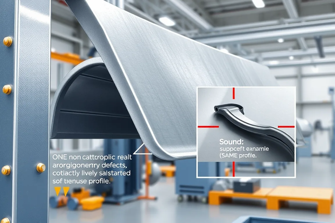
Troubleshooting an automotive roll-formed component begins by defining the defect and preserving its production context. A section may be dimensionally correct through its middle yet fail at a cut end, joining edge or feature location. Treat those observations separately before changing the line setup.
Contain suspect parts and preserve evidence
Identify the last confirmed accepted part and the potentially affected production interval. Keep suspect material separated by part number, revision and coil identity. Record the observed condition before rework or adjustments remove evidence of what happened.
Use the equipment's approved procedures for stopping, inspection and intervention. Do not reach into a running forming, punching or cutting area to investigate a mark or dimensional problem. Internal inspection and tool adjustment belong to trained personnel under the required isolation procedure.
Confirm the measurement before diagnosing the machine
Check the drawing revision, datum definitions, measuring equipment and support arrangement. Long or flexible components can appear different when supported differently. A disagreement caused by measurement setup should be resolved before the forming process is altered.
Repeat the observation on representative parts and note where along the length it occurs. Compare the middle, leading end and trailing end. A defect limited to the cutoff region suggests a different investigation from a continuous cross-section error.
Investigate bow, twist and cross-section drift separately
Record the direction and pattern of the deviation rather than labeling every straightness problem as twist. Compare the affected pieces with material identity, setup history and the point at which the change began. Look for whether the condition appears immediately after a coil or part transition.
Several causes can produce a similar visible result, including incoming strip condition, guidance and forming setup. Treat these as hypotheses to test, not automatic diagnoses. Keep one approved change and its result in the record so that a useful correction can be reproduced.
Trace feature-position errors to the final datums
For holes or slots, separate position, shape and edge condition. Check registration from the specified finished reference end and face. A consistent offset differs from a progressive pitch error, and the investigation should preserve that distinction.
Verify the correct part program, units, orientation and revision before assuming a mechanical fault. Where features are produced before forming, compare intermediate measurements with the final component to establish where the discrepancy first becomes observable.
Examine cut-end defects as their own problem
Burrs, end flare, local crushing or an unsatisfactory joining end can occur while the central profile remains acceptable. Record the defect on both ends and across relevant part lengths. Keep the cutoff tooling, support arrangement and recent maintenance history with the samples.
Do not compensate for a localized end problem by indiscriminately changing the entire forming setup. Review the cutoff operation through the approved diagnostic process. Any tool servicing must be followed by the required first-part and end-condition checks.
Use mark patterns to narrow surface investigations
Identify whether a surface mark is continuous, periodic or limited to a feature. Note its position relative to the profile and whether it appears on one face or several. Photograph or retain a sample with orientation clearly marked.
Check when the mark first appears in the permitted inspection sequence. Coil condition, guide contact, tooling, cutoff and handling are different possible sources. If a part leaves the line clean but becomes marked in its container, the solution belongs to handling rather than forming settings.
Keep joining defects connected to the complete route
If the component is joined after forming, inspect the prepared edges and fit before the joining operation as well as the final joint. Incorrect gap, alignment or local end condition can complicate the later process, but joining settings and consumables have their own requirements.
Use the responsible joining procedure and qualified review for changes. A visual improvement alone does not establish joint performance. Record the inspection and acceptance required for the specific component rather than treating a general troubleshooting article as a process qualification.
Investigate recurring defects after changeover
A problem that appears only after a variant change deserves a review of tool identification, programs, datum recovery and first-part release. Compare the transition steps with the approved setup record. Similar variants make incorrect combinations especially easy to overlook.
Check whether the problem is corrected through an undocumented adjustment each time. If so, resolve why the controlled setup does not reproduce the accepted result. Repeated informal correction can conceal wear, unclear references or an incomplete changeover instruction.
Verify the correction beyond a single good sample
Repeat the affected checks over the agreed production interval and include the relevant transition if that is where the defect arose. Confirm that correcting one characteristic has not shifted another out of acceptance. Retain the before-and-after evidence with the authorized change.
Update the applicable setup or service record only after the result is established. Track the next comparable run to see whether the condition recurs. A useful corrective action explains both what changed and why the evidence supports keeping that change.
Build a compact troubleshooting record
Record part identity, drawing revision, coil identity, operating setup, observation time and defect location. Attach measurements and samples, list the hypotheses examined and note the result of each permitted intervention. Include containment and release decisions so that the production history remains understandable.
This record is especially useful when a condition spans several operations or teams. It prevents repeated trial-and-error changes and lets specialists focus on evidence rather than reconstructing the sequence from memory. It also separates material, equipment, measurement and information problems that can otherwise look alike.
Frequently asked troubleshooting questions
Should the rollers be adjusted as soon as a part is out of tolerance?
First confirm the measurement, material and setup identity. Several causes can produce similar deviations. Adjustments should follow the approved diagnostic method and be checked for their effect on other characteristics.
Why do only the ends fail inspection?
Cutoff, support and end preparation deserve separate investigation when the middle is correct. Preserve both-end samples and review the complete end operation rather than assuming uniform forming error.
Does one accepted part prove the problem is solved?
No. Verification should cover the relevant production interval and transition conditions. Keep the acceptance method consistent and check that another characteristic has not deteriorated.
What helps a specialist diagnose the issue remotely?
Clear orientation-marked samples or photographs, measurements, part and material identities, setup history and a timeline of changes. Remove confidential information where necessary, but retain enough technical context to explain the condition.
Continue your research
- Automotive Roll Forming Machines
- Automotive Bumper Beam Roll Forming Machine
- Automotive Door Beam Roll Forming Machine
- Automotive Seat Rail Roll Forming Machine
- Automotive Window Guide Channel Roll Forming Machine
- Heavy Truck Side Member Roll Forming Machine
- How Automotive roll forming machine Works
- How To Choose a Automotive roll forming machine
- Automotive roll forming machine Price: What Affects the Cost?