
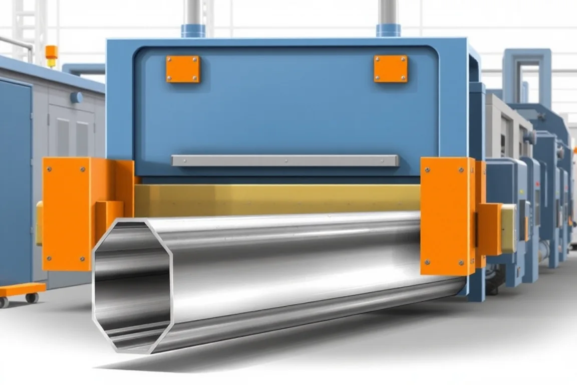
A truck side beam roll forming machine is a production system for forming long, constant-cross-section chassis members from coil. In the automotive category, the machine is defined less by its size than by the part it must deliver: a drawing-controlled side member with a specific material grade, thickness, hole pattern, joining flanges and assembly interfaces. This article walks through the exact finished profile, the interfaces that govern fit-up, the production route, tooling alternatives, separate operations, changeovers, inspection and what constitutes accepted output. It deliberately treats machine selection as a requirements-definition exercise, not a catalogue lookup. No model ratings are claimed here because output depends on the actual profile, material and feature mix.
What the finished truck side beam must be
The finished part is a roll-formed truck side member, typically a long channel, hat or similar open section used in the chassis frame. Its geometry is controlled by a part drawing that fixes the section shape, flange angles, bend radii, overall length and the positions of holes, slots, notches or other features. Because side members often serve as structural load paths, the drawing also sets the datum scheme: the surfaces and features from which all measurements are taken. Two beams that look similar can be functionally different if their datums or joining flanges differ. The form of the finished beam is therefore not simply “a channel” but a set of toleranced dimensions and a defined relationship between the formed section and the assembly interfaces.
Interfaces, holes and joining flanges that govern fit-up
Side beam interfaces usually include the surfaces that mate with crossmembers, brackets, suspension components or body mounts. These interfaces may be pierced holes, slots, weld flanges or sweep features. Each interface has a tolerance and a relationship to the datum scheme. If the drawing requires holes on a flange, the forming process must keep that flange positioned so that piercing, drilling or post-forming operations can locate them reliably. Joining flanges may be designed for spot welding, MIG welding, riveting or bolting, and the flange width, angle and flatness affect how the joint performs. The machine must therefore be evaluated against the interface requirements, not only against the main section. A change in hole pattern or flange width changes tooling and station requirements even when the basic section is unchanged.
The production route from coil to verified beam
A traceable coil feed system introduces material into a series of forming stations that progressively bend the strip into the required section. After forming, feature and cut operations create holes, notches and the final length. Some routes integrate joining or sweep operations; others perform them as separate offline operations. The route ends with dimensional verification against the agreed datums and acceptance criteria. Traceability matters because the material certificate, coil identity and process parameters should be recoverable if a part is questioned later. The production route is not complete at the cutoff; it includes every operation needed to deliver a finished, identified beam. When evaluating a line, map each step to the drawing requirement it satisfies.
Material, grade and thickness inputs
The material is drawing-specified automotive steel or another validated alloy. Grade, strength, coating and allowable variation influence bend radii, pass development and springback compensation. Higher-strength material can require different forming strategies, and the operating thickness range must be verified by the supplier against the actual strip. Buyers should state the base-metal thickness and grade rather than assuming a generic capacity. A machine that forms a mild-steel prototype may behave differently with a higher-strength production material. Material inputs are therefore a primary selection variable, and trial evidence with the intended material is more informative than a demonstration with a substitute.
Tooling alternatives: roll forming, press braking and other routes
Roll forming is one route for long, constant-section parts, but it is not automatically the right one. Press braking can form side members in shorter lengths or lower volumes, though it may add handling and dimensional variation. Stamping can produce complex features but usually involves higher tooling investment and is better suited to shorter parts or high volumes. Extrusion and fabrication from flat plate are alternatives for some geometries. The deciding factors are whether the required part has a constant cross-section, the production volume, the length, and whether holes and joining features can be integrated economically. A part with frequent section changes, extreme thickness or short length may not suit roll forming. The correct choice follows from the drawing and volume, not from the category name.
Feature and cut operations: piercing, notching and cutoff
Features can be created in-line by piercing and notching stations, or offline by drilling, laser cutting or machining. In-line operations reduce handling but add tooling and setup complexity. The cutoff must be profile-supported so that the cut end is square and free from deformation. Cut lengths and end quality are drawing requirements, and secondary operations may be needed to deburr or finish the ends. If holes are pierced after forming, the tooling must account for the formed section and the material springback. If holes are created before forming, the forming process must not distort them beyond tolerance. The choice between in-line and offline features affects cycle time, scrap and the capital cost of the line.
Joining and separate operations
Joining, such as welding brackets or attaching reinforcements, is often a separate operation from roll forming. It may be performed on a fixture using the same datums as the formed beam. Sweeping or bending after forming is another separate operation that changes the beam’s curvature. These operations require their own fixtures, inspection and traceability. The equipment scope should clearly separate production hardware from part-validation responsibilities. A roll forming line may deliver a formed and cut beam, while the finished assembly requires welding, fastening and dimensional verification. Treating those steps as part of the overall production route prevents gaps in responsibility and undeclared costs.
Changeover between side beam variants
Changeover steps depend on how the line is designed. If variants share the same section but differ in hole pattern or length, the change may involve tooling changes, program changes or gauge adjustments. If the section itself changes, more stations or different rolls may be required. Changeover time should include setup scrap, first-off inspection and the time to restore stable production, not only the mechanical adjustment. For a line that will run multiple side beam variants, record each changeover step and measure the associated scrap and downtime. A high continuous feed speed does not describe the time needed to deliver an accepted identified beam. Changeover performance is better assessed with the intended variant mix than with an easy demonstration part.
Inspection, datums and acceptance criteria
Inspection should follow the agreed datum scheme and measurement method. Before tooling approval, the buyer and supplier should agree on which features are critical, how they will be measured, and what acceptance criteria apply. First-off pieces and a representative steady-production sample should be inspected with the agreed gauges. The inspection should cover the formed section, hole positions, flange angles, length and any joining interfaces. Dimensional verification should use the actual material and part configuration, not an easier substitute. Traceability records should link the inspection results to the coil and process conditions. Acceptance is not a single measurement; it is evidence that the process consistently meets the drawing.
Why output and quotation scope must be separated
Production targets are often stated as a rate, but accepted output per shift depends on the profile, material, feature mix, inspection time and handling. A quotation should define whether it includes tooling, trials, gauges, joining equipment, qualification support and spare parts. It should also state the electrical supply requirements, since voltage, frequency and phase are buyer inputs and installed power requires a confirmed equipment schedule. Output should be defined with the actual profile and material, including scrap and changeover allowances. Separating production hardware from part-validation responsibilities clarifies who proves the part meets the OEM requirement. A general roll-forming capability does not demonstrate compliance with a specific part or crash requirement.
Practical selection checklist
- Confirm the drawing-controlled section, datums, holes, joining flanges and assembly interfaces.
- State the material grade, thickness, coating and allowable variation.
- Verify whether the part has a constant cross-section and whether roll forming suits its volume and length.
- Define the feature and cut operations, including cutoff support and end quality.
- Identify joining, sweeping and other separate operations in the production route.
- Agree inspection datums, measurement methods and acceptance criteria before tooling approval.
- Record changeover steps, setup scrap and first-off inspection time for each variant.
- Define accepted output per shift with the actual profile, material and feature mix.
- State voltage, frequency and phase; request a confirmed equipment schedule for installed power.
- Separate production hardware scope from part-validation and qualification responsibilities.
Frequently asked questions
Can a truck side beam roll forming machine produce both left and right side members?
It depends on the section and the tooling arrangement. Mirrored side members may require separate roll sets, reversible stations or a line designed for both orientations. The drawing should define whether the part is handed and how the datums differ between sides. The machine’s capability must be assessed against both variants, not just one.
How should I evaluate a supplier’s claim of high output?
Ask for the basis of the claim: the profile, material, thickness and feature mix used. Accepted output per shift includes inspection, handling and changeover allowances, not only forming speed. Compare the claimed output with a representative steady-production sample run on the intended material.
What is the difference between in-line piercing and offline drilling for side beams?
In-line piercing integrates hole creation into the roll forming line, reducing handling but requiring piercing tooling that accommodates the formed section and springback. Offline drilling or laser cutting offers flexibility for low volumes or complex patterns but adds a separate operation, fixtures and traceability. The choice depends on volume, hole tolerance and capital budget.
Why does the datum scheme matter for inspection?
The datum scheme defines the reference surfaces and features from which all measurements are taken. If the supplier and buyer use different datums, inspection results may disagree even when the part is acceptable. Agreeing the datum scheme before tooling approval prevents disputes and ensures the forming and joining operations use the same reference.
Can one line handle different side beam lengths and hole patterns?
Yes, if the line is designed for changeover. Length changes may involve cutoff adjustments, while hole pattern changes require different piercing tools or program changes. The changeover procedure should be documented, and setup scrap and first-off inspection time should be included in production planning.
What should be included in a quotation for a side beam roll forming line?
A quotation should state the equipment scope, tooling, trials, gauges, joining equipment, documentation, training and qualification support. It should also define the electrical supply requirements and the acceptance criteria. Output should be expressed with the actual profile and material, and the division between production hardware and part-validation responsibilities should be clear.
Accepted output and what it means for planning
Accepted output is the rate of conforming, identified beams that pass the agreed inspection, not the maximum speed of the forming mill. It accounts for first-off inspection, steady-production sampling, scrap and changeover. Planning should use the accepted output figure for the intended variant mix and material. Because no universal rating applies, the buyer should define the target with the actual profile and require the supplier to demonstrate it. That demonstration should use the intended material and include the downstream joining and verification steps needed for a finished part.

Continue your research
- Automotive Roll Forming Machines
- Automotive Bumper Beam Roll Forming Machine
- Automotive Door Beam Roll Forming Machine
- Automotive Seat Rail Roll Forming Machine
- Automotive Window Guide Channel Roll Forming Machine
- Heavy Truck Side Member Roll Forming Machine
- How Automotive roll forming machine Works
- How To Choose a Automotive roll forming machine
- Automotive roll forming machine Price: What Affects the Cost?
Configuration & specification inputs
Match the configuration to your section drawing, material and production requirements.
| Parameter | Requirement / confirmation needed |
|---|---|
| Profile geometry | Truck side members may have long sections and multiple connection features. Assess whether the required part has a constant cross-section and whether roll forming or another fabrication route best suits its geometry and volume. |
| Material | Drawing-specified automotive steel or other validated alloy |
| Thickness & grade | Buyer to specify base-metal thickness and grade; operating range requires supplier verification. |
| Process route | Traceable coil feed → precision forming → feature/cut operations → joining → dimensional verification |
| Cutting | Confirm profile-supported cutoff, cut lengths, end quality and any secondary operations. |
| Output | Define accepted output per shift with the actual profile and material. |
| Electrical supply | Buyer to state voltage / frequency / phase. Installed power requires a confirmed equipment schedule. |
| Acceptance | Use the intended material and feature mix when evaluating output and changeover. Include the required inspections and handling steps. A high continuous feed speed does not describe the time needed to deliver an accepted identified beam. |