
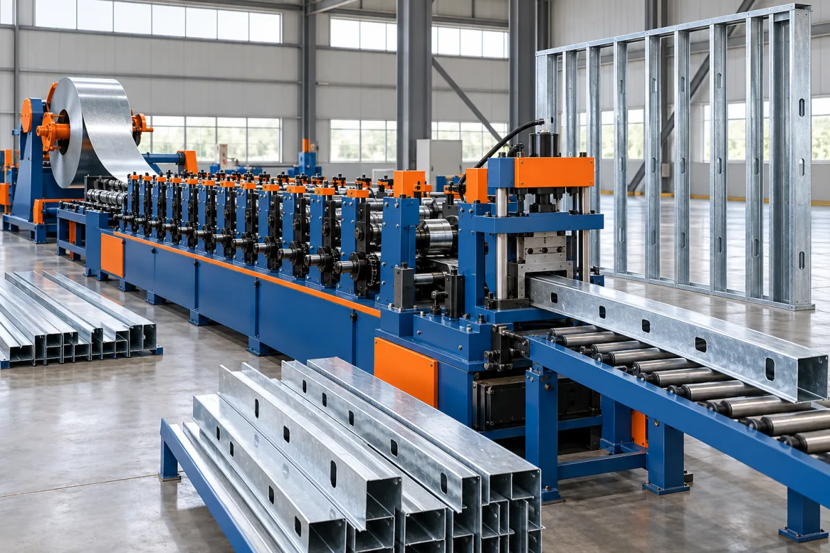
A light gauge steel wall frame machine converts approved wall-member information into formed, featured and identified steel components. Depending on the selected system, those components are then assembled into wall panels using separate equipment or workstations. The purchase should define that boundary clearly rather than assuming a roll former delivers a complete assembled wall.
The distinctive requirement is coordination: studs, tracks, openings, intersections and member labels must agree with the same design revision. A dimensionally correct C section is only one part of the result. The line needs to supply parts that fit the intended wall assembly.
What wall system should be defined first?
Identify the stud and track profiles, material combinations and assembly method. Include headers, jambs, bracing or other components required by the actual design. Some may share the main forming route, while others need different tools or fabrication.
Distinguish structural and nonstructural wall products in the design information. The equipment should manufacture the specified components; it should not infer load-bearing suitability from the fact that a wall frame can be assembled.
How should openings and intersections be represented?
Provide member schedules and details for windows, doors, corners and wall junctions. The associated end preparation and connection features need to be translated into the manufacturing program. A typical straight wall without openings is not a sufficient trial for a varied wall-panel business.
Use clear datums and part identities. Members of similar length may have different holes or orientation because they occupy different positions around an opening. The data and marking system must preserve those distinctions.
Which operations belong on the roll-forming line?
List the required holes, slots, notches, local preparations, length cutting and identification. State which operations the proposed equipment performs and which remain downstream. The feature schedule should follow the approved framing design.
- Connection features for studs and tracks.
- Approved service openings.
- Member-end preparation.
- Assembly labels or marks.
- Special components outside the main section family.
More tools are not automatically better. The useful configuration is the one that makes the required wall components accurately and leaves a clear, manageable downstream process.
How should revisions be controlled?
Define how a released wall design becomes production data and how a later revision is distinguished. Keep project, wall and member identifiers with the program and finished parts. Operators should not need to infer the current version from a filename alone.
When a design changes, review already produced components before starting replacement pieces. A well-formed part from an obsolete wall revision can create the same assembly problem as a manufacturing error. Revision control is therefore part of practical production quality.
What does the manufacturing sequence look like?
Coil preparation supplies the agreed feature-making and forming operations. Progressive tools create the section, the cutoff produces member lengths and marking preserves identity. Parts are then sorted for the specified wall assembly process.
Review the actual order of features and forming with the supplier. Access to a flange or web changes as the section develops. The process must reproduce the required final feature positions without relying on unplanned manual correction.
How should section and assembly quality be separated?
First inspect web, flanges, lips, angles, length and feature registration. Use the agreed material and supports, and check local end condition. These measurements establish whether individual members match their drawings.
Then assemble a representative wall panel with an opening and relevant intersections. Check overall geometry, member fit and part identification. Record extra cutting, forcing or drilling rather than treating it as an invisible part of the demonstration.
What material and profile changes should be trialed?
Pair each section with grade, base-metal thickness and coating. If the business will make several wall depths, request the complete tooling and program-change scope. Similar C-shaped members may use different tracks and connection references.
Demonstrate first-piece recovery after a meaningful change and verify the corresponding assembly fit. A section that measures correctly but no longer mates with its intended track is not a complete success.
How should output be stated for wall production?
- Define a representative wall schedule and feature density.
- State whether output stops at members or assembled panels.
- Include sorting, marking and required profile changes.
- Count accepted components and record rejected pieces.
- Measure downstream assembly work separately where useful.
- Retain the design revision used for the trial.
This prevents an isolated metres-per-minute figure from being confused with completed walls per shift. The two measures describe different scopes and should not be compared without explanation.
Frequently asked questions
Does the machine assemble the wall automatically?
Only if assembly equipment is explicitly included. Many forming routes deliver prepared members that are assembled at a separate station. Define the required finished output before comparing quotations.
Can it make every wall depth?
No universal range should be assumed. List the actual section families, materials and mating tracks so the supplier can define the supported combinations and change parts.
Why test a wall with an opening?
Openings introduce different member lengths, orientations and connections. They reveal data and assembly issues that a simple uninterrupted wall sample may not show.
Can labels be omitted to save time?
For project-specific members, reliable identification often prevents larger sorting and assembly problems. Define a marking method appropriate to the workflow and finish requirements.
What should the first acceptance project contain?
A representative wall with normal studs and tracks, at least one opening and relevant connection details. Use the actual data path and material so the trial reflects everyday production.
Judge the route by assembly-ready wall components
The strongest wall-frame specification links design revision, features, section accuracy and member identity. That gives the equipment trial a practical goal and makes the boundary between forming and wall assembly easy to understand.

Continue your research
- Stud & Track Roll Forming Machines
- Drywall Stud Roll Forming Machine
- Drywall Track Roll Forming Machine
- C89 Light Gauge Steel Framing Machine
- C140 Light Gauge Steel Framing Machine
- Top Hat Light Steel Framing Machine
- How Stud and track roll forming machine Works
- How To Choose a Stud and track roll forming machine
- Stud and track roll forming machine Price: What Affects the Cost?
Configuration & specification inputs
Match the configuration to your section drawing, material and production requirements.
| Parameter | Requirement / confirmation needed |
|---|---|
| Profile geometry | Approved stud, track and special wall-component families tied to the wall assembly design. |
| Material | Specified steel grade and coating for each structural or nonstructural wall component. |
| Thickness & grade | Section-specific base-metal thickness combinations with controlled mating-track references. |
| Process route | Released wall data, feature operations, forming, cutting, marking, sorting and separately scoped assembly. |
| Cutting | Project member lengths and end details linked to wall and drawing revision. |
| Output | Accepted identified members or assembled walls with the production boundary explicitly stated. |
| Electrical supply | Utilities for the selected forming and feature tools plus any included assembly equipment. |
| Acceptance | Member geometry, features, revision and orientation, opening details and complete representative wall fit. |