
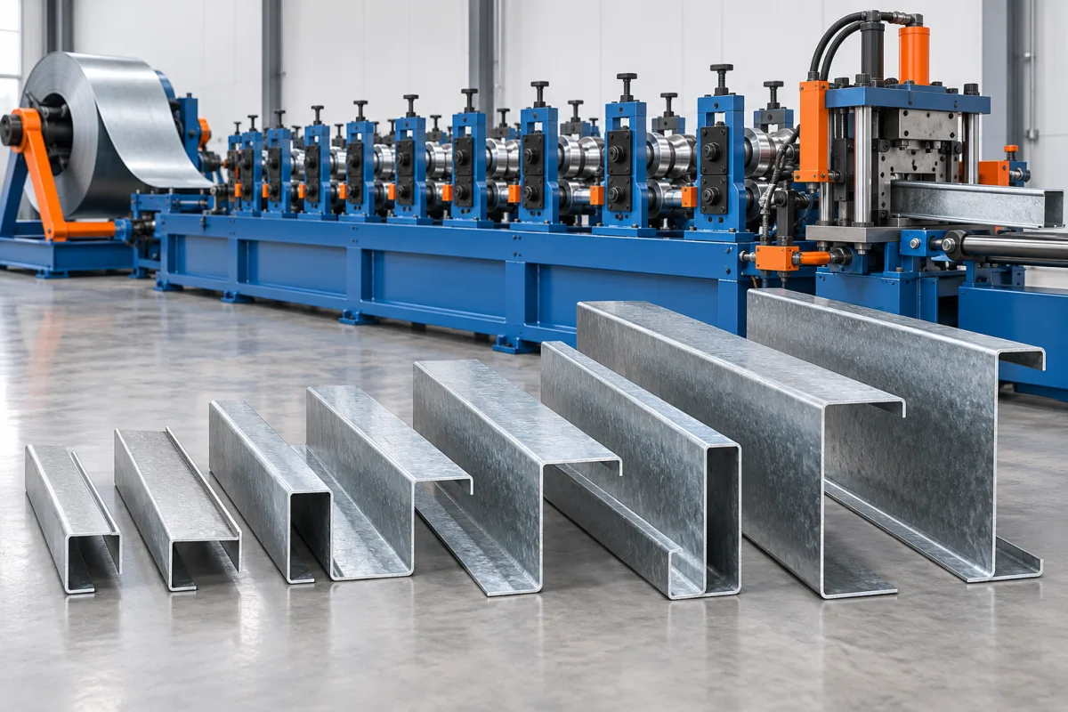
A variable size purlin roll forming machine is intended to manufacture a defined family of sections rather than one fixed profile. The important word is defined: web, flange, lip, material and connection requirements must be listed as approved combinations. Variable size does not mean every dimension can change independently or every possible purlin is included.
The equipment decision should start with the product catalogue and order pattern. A business needing several standard web depths has a different requirement from one producing frequent custom flanges, special lips and multiple section families. The proposed adjustment system should match those actual needs.
Which dimensions are intended to vary?
List web depth, flange widths, lips and bend details separately. Identify whether the range contains C, Z, U or other profiles. A machine that adjusts one web dimension may not support a new flange relationship or a different profile family.
For every target product, pair dimensions with material grade and thickness. This avoids creating an imaginary envelope by combining unrelated maximum values. Ask the supplier to mark each combination as covered, requiring different tools or outside the proposed scope.
How should the product matrix be organized?
Give each section a controlled identifier and drawing revision. Record material, input width, hole program, lengths and required tools. A clear matrix helps both equipment evaluation and later order entry.
- Separate standard catalogue sizes from custom variants.
- Identify frequently repeated transitions.
- Mark sections that share coil width or tools.
- Show connection features and orientation.
- State the first-piece checks for each family.
The matrix should be understandable to operators and purchasing staff as well as engineers. Ambiguous product names create avoidable mistakes when several similar sections share one line.
What adjustment methods should be compared?
Possible proposals may use manual adjustments, automated positioning, exchanged tooling or combinations of these approaches. Compare the complete work required to reach the next accepted product. A method that is convenient for web changes may be less useful for frequent lip or flange changes.
Ask how settings are recorded and verified. The important result is reproducible geometry with the correct material and tools, not a particular automation label. Include inspection and startup scrap when evaluating setup efficiency.
How do punching and cutting limit flexibility?
Feature positions and cutoff support must suit every approved section. A flexible forming mill does not make a fixed punch layout or one cutting die universal. List the feature tools and cutting components required by the product matrix.
Trial actual holes and end conditions after a size change. Finished-member datums should remain clear even when the section changes. A correct web depth is insufficient if the connection holes or cut-to-hole relationship are wrong.
How should coil stock be considered?
Different sections may need different developed strip widths. Define which products share stock and which require a coil change. Do not assume that one input width can make all sizes simply because the line is adjustable.
Include coil-change work in schedule comparisons or state explicitly when it is excluded. Material inventory and change frequency can strongly influence whether a broad variable-size catalogue is practical for the business.
What should be checked at the edges of the range?
Choose trial cases representing the smallest, largest and otherwise demanding combinations. Narrow flanges, long lips, thick material or special holes may create different challenges from maximum web depth alone. The trial plan should reflect those distinctions.
Measure section dimensions, angles, straightness, twist and end condition using agreed supports. Keep each result tied to its material and setup. That makes the approved range evidence-based instead of a collection of unrelated samples.
How can order scheduling improve the result?
Group orders sensibly around shared material and tooling where business requirements allow. Evaluate the actual transition frequency rather than assuming every order begins from the same setup. The machine proposal should support the intended schedule without dictating an impractical sales catalogue.
Define identification and bundle separation for similar products. Flexible production creates more opportunities to mix dimensions or hole patterns downstream. Clear part identity is part of delivering correct orders from a shared line.
What should acceptance demonstrate?
- Confirm the approved section and material matrix.
- Run representative normal and boundary combinations.
- Demonstrate meaningful changes in web, flange or profile family.
- Verify punching and cutoff after each transition.
- Inspect dimensions, straightness and connection fit.
- Record accepted mixed-order output and startup waste.
- Document required tools and settings for repeat production.
Use this record to compare flexibility with a dedicated-line alternative. More variants are valuable only when the business can make them reliably and economically within its real order pattern.
Frequently asked questions
Does variable size mean infinitely adjustable?
No. The equipment has an engineered range and permitted combinations. Define the actual required products and obtain a clear scope for each one.
Can every dimension change independently?
Not necessarily. Web, flange, lip and strip width can be linked by the tooling arrangement. Ask for the supported combination matrix rather than separate ranges alone.
Will one coil width cover the whole catalogue?
Only where the developed sections permit it. Confirm input width for every approved product and include necessary coil changes in production planning.
Why test holes after a size change?
The forming adjustment may require different feature references or tooling positions. Checking the final member confirms that connection geometry changed correctly with the section.
What is the best evidence of useful flexibility?
A mixed-order trial that produces accepted members across representative combinations, with change time, manual tasks and startup scrap recorded. A wide nominal range alone is not enough.
Define flexibility around the products you will sell
A variable-size purlin line should serve a controlled, practical catalogue. Connecting every section to material, tools and acceptance makes flexibility understandable and turns a broad machinery claim into a usable manufacturing plan.

Continue your research
- Purlin Roll Forming Machines
- C Purlin Roll Forming Machine
- Z Purlin Roll Forming Machine
- 80-300mm CZ Purlin Roll Forming Machine
- 100-400mm CZ Purlin Roll Forming Machine
- Automatic Size Change CZ Purlin Machine
- How Purlin roll forming machine Works
- How To Choose a Purlin roll forming machine
- Purlin roll forming machine Price: What Affects the Cost?
Configuration & specification inputs
Match the configuration to your section drawing, material and production requirements.
| Parameter | Requirement / confirmation needed |
|---|---|
| Profile geometry | Controlled variable-section catalogue with explicit web, flange, lip and profile-family combinations. |
| Material | Grade and coating assigned to every approved catalogue member. |
| Thickness & grade | Per-product thickness and developed strip width rather than independent maximum values. |
| Process route | Order and tool selection, defined adjustments, punching, forming, cutting and traceable bundling. |
| Cutting | Cutoff components and end-feature references confirmed for every approved section family. |
| Output | Accepted mixed-order members including meaningful dimensional changes, inspection and startup waste. |
| Electrical supply | Utilities for the complete configurable forming and auxiliary-equipment schedule. |
| Acceptance | Normal and boundary combinations, feature registration, geometry, straightness and repeatable setup records. |