
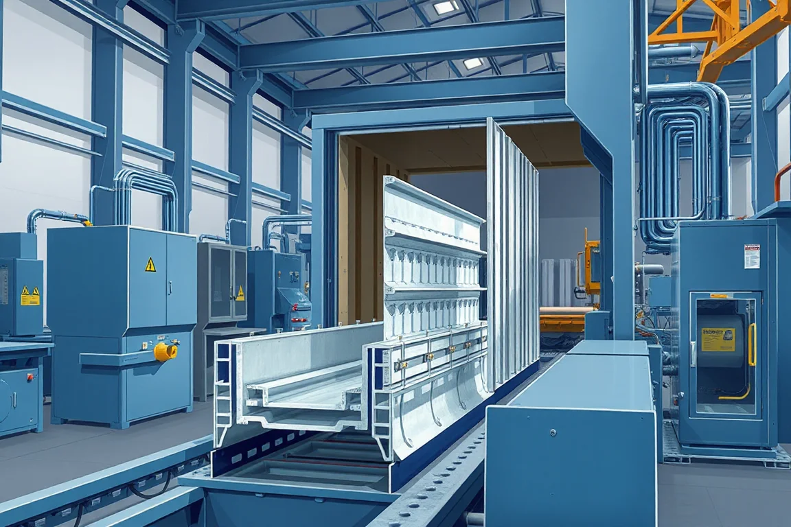
Production speed and output of a door frame roll forming machine cannot be reduced to a single number quoted by a supplier. The line speed that matters for planning is the steady forming rate that the machine can sustain while producing a frame that passes inspection, and the output that matters is the number of acceptable finished frames per shift after features are punched, the profile is cut to length, and corners are assembled and checked. A machine may form strip quickly, but if hinge and latch punching, cut length changes, or corner joining limit the flow, the accepted output will be lower. This guide explains how speed and output are determined, what decisions affect them, and how to assess a line against a representative door schedule.
Why a single speed figure is not the output rate
Roll forming lines are often described by a steady running speed, but that figure says little about finished frame output. The line includes material preparation, feature punching, forming, cutoff, and corner assembly. Each step can impose its own cycle time. If punching a hinge reinforcement takes longer than forming a metre of profile, the punching station sets the pace. If the cutoff must dwell for a clean end and a specific cut length, the cutoff cycle affects the average speed. If the frame is assembled and checked away from the line, assembly labour and inspection time can reduce the number of frames that reach dispatch. For planning, separate the steady forming speed from the overall accepted output per shift. The only meaningful output calculation uses actual running minutes, the proportion of good material, and the real product mix.
How the sequence creates and limits output
The production sequence begins with blank or coil preparation, then feature punching, frame forming, cutoff, and finally corner assembly and inspection. Each interface between steps is a potential bottleneck. Coil changes interrupt running time and require threading, alignment, and scrap removal. Feature punching needs the correct tool set for hinge positions, latch slots, and other cutouts; changing from one door schedule to another may require tool changes and trial runs. Forming stations must handle the specified material and thickness without distorting the profile or causing edge waviness. The cutoff must produce the required cut length and end quality without deforming the section. Corner assembly may involve welding, crimping, or mechanical joining, and the resulting frame must be checked for square and hardware fit. Output is limited by the slowest of these operations when the line runs continuously, or by the longest setup when the product mix changes frequently.
Steady running speed versus accepted output per shift
Steady running speed is the rate at which the machine forms continuous profile under stable conditions. Accepted output per shift is the amount of finished frame that passes inspection and can be used. The difference includes coil changes, setup, punching cycles, unplanned stops, rejected material, and rework. A machine with a high steady speed but slow punching and frequent tool changes may produce fewer accepted frames than a slower machine with quick-change features. When evaluating a line, ask for the steady speed separately from the expected accepted output, and treat any quoted output as a planning estimate that must be verified with a representative door schedule. Do not assume that a value from one profile applies to another.
The real bottleneck: identify it before comparing machines
Bottleneck identification is a practical exercise. Track the time spent at each stage for a representative set of frames: preparation, punching, forming, cutoff, and assembly. The stage with the longest average duration or the highest variability is the likely bottleneck. If punching time varies with hinge pattern, that is a bottleneck. If cutoff requires a slow deceleration and acceleration for each cut length, that is a bottleneck. If corner assembly requires rework because the formed profile does not match the hardware, that is a bottleneck. The bottleneck may shift with product mix; a line that is balanced for one frame type may be limited by a different operation for another. Use the bottleneck to decide which features to prioritise: quick-change punching tools, servo cutoff, or in-line joining.
Feature punching and hardware positions
Feature punching covers hinge reinforcements, latch and lock cutouts, and any other openings required by the door hardware. The number, position, and complexity of these features affect cycle time. A single punch may be fast, but a cluster of punches or a contoured cutout may require a slower press cycle or a separate operation. Hardware positions must match the door schedule; if the line is expected to produce multiple schedules, tooling changes and position adjustments add to setup time. When comparing machines, ask how the punching tooling is changed, how positions are set, and whether the punch cycle can run while forming continues. The goal is to avoid stopping the line for each feature set. For output planning, count the punching time separately from the forming time.
Cutoff, cut length, and secondary operations
The cutoff determines the finished length of the frame section. It must produce a clean end that suits the corner joint without creating burrs or distortion. Cut length changes may require adjustment of the cutoff die or a different tool, and each change consumes time. Some lines use a flying cutoff that cuts while the profile moves; others stop the line for each cut. A flying cutoff can maintain higher average speed, but it may not be suitable for every profile or material. Secondary operations such as notching, embossing, or labelling also affect cycle time. When assessing output, treat the cutoff as a cyclic event: the number of cuts per frame and the time per cut both count. If the line produces multiple cut lengths from one strip, the cutoff cycle may become the limiting factor.
Corner assembly and why it is separate from line speed
Corner assembly joins the cut sections into a frame. It may be done in-line or off-line, manually or automatically. Assembly is often a separate constraint because it depends on the accuracy of the formed profile, the squareness of the cut ends, and the hardware fit. A fast forming line can produce a stock of unassembled sections that then wait for assembly, so the finished frame output is governed by the assembly rate, not the forming rate. Assembly also affects quality: a frame that is not square or has poorly aligned rebates will be rejected, reducing accepted output. For planning, measure the assembly time per frame and include it in the overall output calculation. If assembly is manual, labour availability and skill become part of the output equation.
How material and thickness influence speed and output
The specified sheet steel grade and thickness affect forming speed and tooling life. Thicker or higher-strength material may require slower forming to avoid cracking, excessive springback, or distortion. Stainless steel and other alloys often need separate tooling validation because they work-harden differently and may require different roll geometry or lubrication. The operating range for thickness and grade is not universal; it must be verified for the specific profile and material. When planning output, use the material and thickness that will actually be run. A line that performs well on one thickness may need to run slower on another to maintain quality. The accepted output per shift should be based on the worst-case material in the schedule, not the easiest.
What a production speed quote should include
A supplier quote for production speed should define the scope clearly. It should state the profile or profiles assumed, the material grade and thickness, the feature punching pattern, the cut length, and whether corner assembly is included. It should distinguish between steady running speed and expected accepted output per shift. It should state the running minutes assumed and the allowance for coil changes, setup, and maintenance. Without this scope, a speed figure is not comparable between suppliers. Ask for the basis of the estimate and whether it is based on a trial with a representative profile. If the quote does not include assembly and inspection, the finished frame output may be lower.
Calculating accepted output without fabricated numbers
Accepted output can be estimated by multiplying the steady running speed by the actual running minutes and by the good-output fraction, then dividing by the representative cut length if the product mix and cutoff cycle permit that simplification. This calculation is only as good as its inputs. The steady running speed must be the speed for the actual profile and material, not a generic value. The running minutes must exclude coil changes, setup, and breaks. The good-output fraction must account for rejected or reworked material. The cut length must be the intended length for the frame section, and the number of sections per frame must be known. For a more accurate estimate, track the time for each stage separately and use the bottleneck rate to calculate output. Because every profile and schedule is different, no single numerical example applies universally; use the calculation as a framework, not a prediction.
Practical checklist for evaluating speed and output
- Define the representative door schedule: frame size, hardware positions, and corner type.
- List the material grade and thickness for each profile in the schedule.
- Measure the steady running speed for each material and profile, not just one.
- Count the punching operations per frame and measure the cycle time for each pattern.
- Record the cutoff cycle time and the time to change cut lengths.
- Measure the corner assembly time per frame, including any fitting or adjustment.
- Track coil change time and setup time between different profiles.
- Separate good output from rejected or reworked material.
- Identify the bottleneck stage for each product type.
- Calculate accepted output per shift using actual running minutes and good-output fraction.
- Verify the estimate with a trial run on a representative schedule if possible.
- Confirm that assembly and inspection are included in the output figure.
Comparing machine alternatives for speed and output
Machines differ in how they handle the sequence. A line with a flying cutoff and quick-change punching may maintain higher average speed on long runs but may have higher tooling cost and complexity. A line with a stationary cutoff and manual tool changes may be slower to change over but simpler and less expensive. A line with in-line corner assembly reduces handling but may require more floor space and integration. A line with off-line assembly allows forming to continue while assembly catches up, but it creates work-in-progress and may need more labour. The right choice depends on the product mix: if the schedule changes frequently, setup time and tool change speed matter more than steady running speed. If the schedule is stable, steady speed and cutoff cycle dominate. Consider the total accepted output per shift for the actual mix, not the peak speed of any single station.
Quality checks that affect accepted output
Accepted output depends on quality. Inspect rebates and seal lands for dimensional accuracy and surface finish. Test actual hardware on the finished frame, including hinges and latch, to ensure the punched features align. Test a representative corner joint for strength and squareness. Measure the finished frame after assembly as well as the unjoined section, because assembly can introduce distortion. If the frame is intended for a fire-rated assembly, note that forming a frame does not certify a fire rating; the rating depends on the complete tested and approved door system, including installation. Rejected frames reduce output and may require rework, so quality checks should be part of the output calculation.
Frequently asked questions
What determines the production speed of a door frame roll forming machine?
The production speed is determined by the steady forming rate for the specific profile and material, but the overall output is determined by the slowest stage in the sequence: preparation, punching, forming, cutoff, or corner assembly. Feature punching and cutoff cycles often limit average speed more than forming itself. The accepted output per shift also depends on setup time, coil changes, and the proportion of good frames.
How can I estimate accepted output per shift without a trial?
Use a structured estimate: multiply the steady running speed by the actual running minutes and by the good-output fraction, then divide by the representative cut length if the product mix and cutoff cycle allow that simplification. Include allowances for coil changes, setup, punching, and unloading explicitly. Because every profile and schedule is different, treat the result as a planning estimate and verify it with a trial on a representative schedule.
Does a higher line speed always mean more finished frames?
No. A higher steady forming speed may be offset by slower punching, cutoff, or assembly. If the bottleneck is elsewhere, increasing forming speed may only create work-in-progress. Finished frame output depends on the whole sequence and on quality; a line that produces fast but requires rework may have lower accepted output than a slower, more consistent line.
Why is corner assembly often the limiting factor?
Corner assembly is often manual or semi-automatic and depends on the accuracy of the formed profile and cut ends. If assembly is slow or requires adjustment, it limits the rate at which finished frames are produced, even if forming is fast. Assembly also affects squareness and hardware fit, so it is both a rate constraint and a quality gate.
How does material thickness affect forming speed?
Thicker or higher-strength material may require slower forming to avoid cracking, excessive springback, or distortion. The operating range for thickness and grade is not universal; it must be verified for the specific profile and tooling. Output planning should use the actual material and thickness, not a generic value.
What should be included in a supplier's speed quote?
A speed quote should state the profile, material grade and thickness, feature punching pattern, cut length, and whether corner assembly is included. It should distinguish steady running speed from expected accepted output per shift and state the running minutes and allowances assumed. Without this scope, speed figures are not comparable between suppliers.
Continue your research
- Door & Window Profile Roll Forming Machines
- Steel Door Frame Roll Forming Machine
- Window Frame Roll Forming Machine
- Hollow Metal Door Frame Roll Forming Machine
- Garage Door Track Roll Forming Machine
- Door Reinforcement Channel Roll Forming Machine
- How Door frame roll forming machine Works
- How To Choose a Door frame roll forming machine
- Door frame roll forming machine Price: What Affects the Cost?