
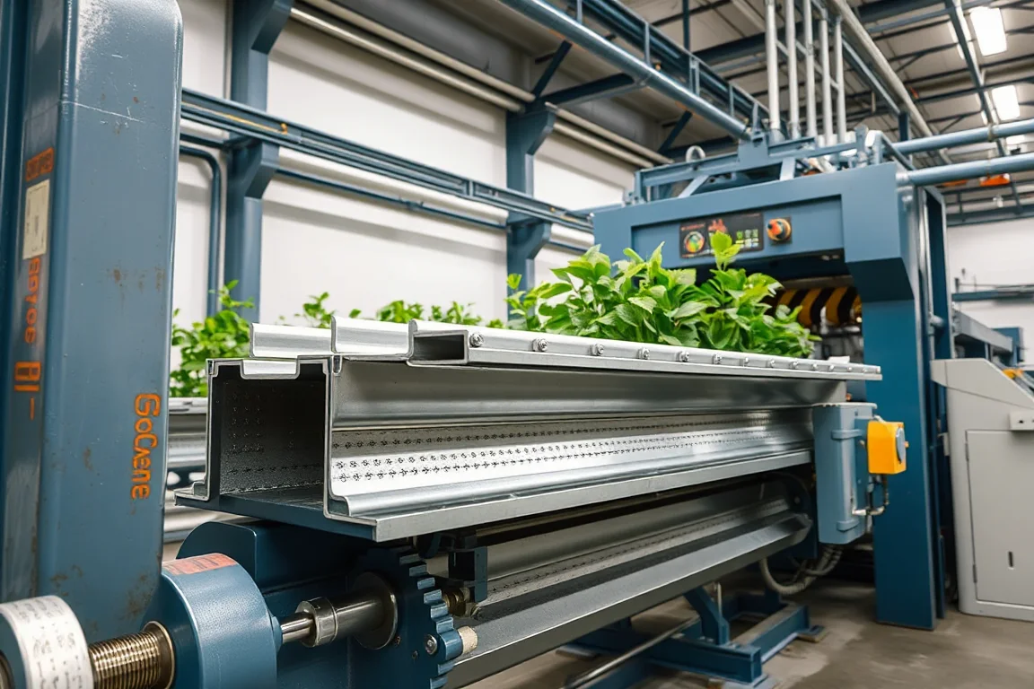
A greenhouse crop support channel is not simply a bent strip of metal. It is a load-bearing interface between the structure of the greenhouse and the plants, trellis wires, clips, or trolleys that hang from it. The machine that produces it—often described as a greenhouse crop support channel machine—is a roll forming line configured around a specific section drawing and a specific connection pattern. This article explains what that machine does, how it differs from neighboring profile lines, and how to judge whether a proposed production route fits the application.
What the crop support channel actually does in a greenhouse
In a greenhouse, the crop support channel typically runs horizontally beneath the gutter or along the bay, providing a continuous rail from which plant support hardware is suspended. It may also serve as part of a crop wire system, a trolley track for internal transport, or a mounting rail for clips and hooks. The channel is not the same as a structural column, a gutter, or a film-locking profile, although it may share the same material and forming equipment family. Its defining feature is the connection interface: holes, slots, or formed features that accept hooks, clips, brackets, or wire anchors at predictable positions. The structural design of the greenhouse determines the required section dimensions and the allowable load per connection; the roll forming machine must reproduce the drawing that carries those connections.
Component production versus assembly and in-service performance
Roll forming produces the channel section, the connection holes, and the cut length. That is the component. Assembly is a separate stage: attaching brackets, joining lengths, installing the channel into the greenhouse frame, and fitting the crop support hardware. Certification, if required, applies to the assembled system or to the structural design, not to the fact that a profile was roll formed. In-service performance depends on the installed support spacing, the actual loads, the corrosion environment, and the interaction between the channel and the fittings. A production line can make a dimensionally accurate channel that is unsuitable for a particular greenhouse if the connection pattern or material protection is wrong for that environment. Keeping these boundaries clear prevents over-reliance on the forming machine as a guarantee of structural adequacy.
Profile drawing and connection features: what the machine must reproduce
The starting point is the profile drawing. For a crop support channel, the drawing usually defines the outer section shape, the position and size of holes or slots for hooks and clips, and any formed lips or returns that stiffen the section or retain hardware. The machine sequence must include punching or drilling for those connection features, either before or after forming depending on the line configuration. If the channel includes a gutter drainage shape or a film-lock channel as a secondary function, the drawing will show those features as well, but the crop support interface remains the critical feature for this application. The machine must be set up to produce the hole pattern consistently over the full production length, because a single misplaced hole can make a connection point unusable.
Material and corrosion environment: protected metal versus plastic
Crop support channels discussed here are protected metal sections—typically steel with a coating or finish intended to resist humidity, condensate, and nutrient solutions. The specific base metal thickness and grade are buyer-defined inputs, and the operating range of any machine requires supplier verification. Plastic growing channels, such as those used in nutrient film technique systems, are produced by extrusion, not roll forming. A metal gutter line is not a substitute for a plastic extrusion system, and the two should not be compared as if they were interchangeable. Within metal channels, the choice of protection matters: a coating that performs in a dry climate may not last in a wet, chemically active greenhouse. Specify the expected environment rather than relying on a generic galvanized description.
Roll forming process route for crop support channels
A typical route for a metal crop support channel is: coil preparation, connection punching, section forming, cutoff, and greenhouse-interface checks. Coil preparation involves loading and feeding the strip; punching creates the holes or slots for hooks and clips; forming progressively shapes the section through a series of roll stands; cutoff produces the required length; and interface checks confirm that the finished piece matches the drawing at the connection points. The order of punching and forming can vary. Punching before forming can be efficient for simple hole patterns, while punching after forming may be necessary for features that would distort during bending. The cutoff must be compatible with the profile shape so that it does not crush or deform the section at the ends.
Punching, forming, and cutoff: how they interact
Punching is not just a hole-making step; it is the step that defines the crop support interface. The punch tooling must match the hook, clip, or bracket that will be used. If the greenhouse design uses proprietary clips, the hole size and spacing must be confirmed against those clips. Forming then shapes the section around the punched features, and any distortion from forming can alter hole position or roundness. Cutoff separates the finished length and should be chosen so that the cut end is clean enough for the joining method—whether that is a connector, a splice plate, or a bracket. Secondary operations such as bending, notching, or end forming may be required for some greenhouse designs; these should be listed in the equipment scope if they are needed to complete the part.
Distinguishing crop support channels from neighboring profile types
A greenhouse uses several unrelated profile functions, and each may have its own machine configuration. A film locking channel is designed to grip and retain plastic film; its section and retaining elements are specific to that task. A purlin is a structural member that carries roof or wall loads. A steel column is a vertical structural element. A guide rail may be used for moving equipment or curtains. A crop support channel carries application-specific connections and loads, and its section is shaped by the hooks, clips, or hanging elements defined in the greenhouse design. These profiles may be produced on similar roll forming equipment, but the tooling and the acceptance criteria differ. Treating them as interchangeable can lead to a machine that forms metal accurately but fails at the interface that matters.
Interface checks: film-retaining hardware, drainage joints, and connection holes
Acceptance for a crop support channel focuses on the interfaces. Check the hole pattern over a useful production length and test the specified fittings. Confirm that film-retaining hardware fits if the channel includes a film-lock feature. Review drainage joints if the channel also functions as a gutter. For growing systems, evaluate suitability for the actual nutrient and cleaning environment, including the effect of cleaning agents on the coating and cut edges. The allowable supported load comes from the engineered assembly, not from the fact that the channel is roll formed. These checks are not a substitute for structural design; they verify that the component matches the drawing that the design assumes.
Production target, electrical supply, and output planning
There is no verified model rating for output that applies across profiles and materials. Define accepted output per shift with the actual profile and material. A line that runs one section at a moderate pace may run a different section faster or slower depending on the number of punching operations and the forming complexity. The buyer should state the required voltage, frequency, and phase for the electrical supply; installed power requires a confirmed equipment schedule rather than an assumption. Output planning should also account for changeover time, setup scrap, and the handling of long members. Long crop support channels can be awkward to stack and move, so the layout of the line and the unloading area matters as much as the forming speed.
Output and quotation scope: separating forming from secondary operations
When requesting a quotation, separate structural profiles, gutters, film-lock components, and crop support channels. Each may have different tooling and acceptance criteria. Additional bending, punching beyond the connection holes, and assembly may be outside the forming scope, so they should be quoted separately if they are needed. The quotation should state what the machine produces and what remains to be done to create a finished, installable part. For a crop support channel, the finished part includes the correct connection features and any required end treatments. If the greenhouse design requires curving or joining operations, those must be included in the scope or handled separately with a clear handoff point.
Practical checklist before approving a production line
- Run the agreed material and profile, not an easier demonstration substitute.
- Inspect first-off pieces and a representative steady-production sample with the agreed gauges.
- Verify the connection hole pattern against the greenhouse drawing and the specified fittings.
- Confirm that the cutoff produces ends suitable for the intended joining method.
- Record changeover steps, setup scrap, punching time, and unloading time.
- Compare the written equipment scope with all secondary operations needed for a finished part.
- Review coating and cut-edge requirements for the actual greenhouse environment.
- Confirm that the electrical supply and installed power are documented in the equipment schedule.
Comparing production route alternatives for crop support channels
Roll forming is one route for metal crop support channels; other routes include press braking, stamping, or extrusion for plastic channels. Roll forming is suited to long, constant-section profiles with repeating connection features, and it can integrate punching and cutoff in a continuous line. Press braking is more flexible for short runs or complex bends but slower for long lengths and less consistent for hole patterns. Stamping can produce connection features efficiently but does not form the section. Plastic extrusion is the appropriate route for plastic growing channels, where the material and the process differ fundamentally. The choice depends on the section geometry, the material, the required length, and the connection interface. A metal gutter line is not a substitute for a plastic extrusion system, and a press brake is not a substitute for a roll forming line when long, uniform sections are required.
FAQ
What is the difference between a crop support channel machine and a film locking channel machine?
A crop support channel machine is configured to produce a section that carries hooks, clips, or hanging loads, with connection features defined by the greenhouse design. A film locking channel machine produces a section designed to retain plastic film, with a different profile and different retaining elements. The tooling and acceptance criteria differ even if the machines look similar.
Can I use a metal roll forming line to make plastic hydroponic channels?
No. Plastic growing channels are typically produced by extrusion, which is a different process using different equipment and tooling. A metal roll forming line is not a substitute for a plastic extrusion system, and the two should be evaluated separately for the material and application.
How do I determine the allowable load for a crop support channel?
The allowable supported load comes from the engineered assembly, not from the fact that the channel is roll formed. The structural design of the greenhouse, the support spacing, the connection details, and the material properties all contribute. The machine supplier can confirm what the line can form, but the load capacity must come from the structural design.
What should be inspected on a first-off crop support channel?
Inspect the connection hole pattern against the greenhouse drawing over a useful production length, test the specified fittings, check the section dimensions with the agreed gauges, and verify that the cutoff ends are suitable for the intended joining method. If the channel includes a film-lock or drainage feature, check those interfaces as well.
Why is the electrical supply and installed power a buyer input?
The buyer must state the voltage, frequency, and phase because the equipment must match the available supply at the installation site. Installed power requires a confirmed equipment schedule; it cannot be assumed from a generic description. These are site-specific inputs that affect the electrical design of the line.
What secondary operations might be needed for a finished crop support channel?
Secondary operations can include bending, additional punching, end forming, or assembly of brackets and connectors. These may be outside the roll forming scope and should be listed separately in the quotation. The finished part must match the greenhouse drawing, including any curving or joining required by the installation.

Continue your research
- Greenhouse Profile Roll Forming Machines
- Greenhouse Gutter Roll Forming Machine
- Greenhouse Channel Roll Forming Machine
- Greenhouse Film Locking Channel Machine
- Greenhouse Purlin Roll Forming Machine
- Greenhouse Steel Column Roll Forming Machine
- How Greenhouse roll forming machine Works
- How To Choose a Greenhouse roll forming machine
- Greenhouse roll forming machine Price: What Affects the Cost?
Configuration & specification inputs
Match the configuration to your section drawing, material and production requirements.
| Parameter | Requirement / confirmation needed |
|---|---|
| Profile geometry | Crop-support channels carry application-specific connections and loads. Define the hooks, clips or hanging elements and obtain the required structural design before selecting section dimensions. |
| Material | Specified protected metal sections; plastic growing channels use a different process |
| Thickness & grade | Buyer to specify base-metal thickness and grade; operating range requires supplier verification. |
| Process route | Coil preparation → connection punching → section forming → cutoff → greenhouse-interface checks |
| Cutting | Confirm profile-supported cutoff, cut lengths, end quality and any secondary operations. |
| Output | Define accepted output per shift with the actual profile and material. |
| Electrical supply | Buyer to state voltage / frequency / phase. Installed power requires a confirmed equipment schedule. |
| Acceptance | Measure the hole pattern over a useful production length and test the specified fittings. Include coating and cut-edge requirements. The allowable supported load comes from the engineered assembly, not from the fact that the channel is roll formed. |