
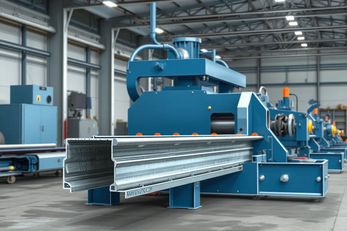
A greenhouse channel roll forming machine produces long, thin-gauge metal sections that hold plastic film, carry condensate, connect structural members or support growing hardware. The equipment category is broad because the word channel covers several unrelated functions. A film-lock channel, a gutter, a post and a crop-support rail can all be described as channels while sharing almost nothing in opening geometry, joint detail or connection pattern. The machine only becomes a sensible purchase when it is matched to one finished profile and one defined job in the greenhouse.
This page explains what the finished section actually is, which interfaces it must satisfy, how the production route is organised, where tooling alternatives diverge, and how to inspect output against the greenhouse drawing rather than against a catalogue label.
What the finished greenhouse channel must do
A finished channel is a formed metal section with a constant cross-section along its length, produced from coil by progressive rolls and then cut to length. Its value comes from three things at once: the section the rolls create, the holes and cutouts added before or after forming, and the ends produced at cutoff. A channel that forms cleanly but whose holes miss the bracket pattern is not a usable part.
Function determines geometry. A film-retention channel needs an opening sized and shaped so the retaining wire or profile presses film into the slot without tearing it. A drainage channel needs a floor and walls that direct water toward an outlet and a joint detail that does not leak at the seam between lengths. A structural channel needs flange and web proportions that resist the loads the greenhouse frame imposes. A crop-support or growing channel needs surfaces and openings suited to the actual nutrient, cleaning and humidity environment, which is a corrosion question as much as a forming question.
Because these functions pull the design in different directions, a single roll set usually cannot serve all of them. Treat each channel type as its own part number with its own drawing revision.
The interfaces that define acceptance
Acceptance is decided at the interfaces, not at the middle of the section. For a film-lock channel the critical interface is the retaining element: the wire, spring clip, clamp or profile that traps the film. The channel groove must accept that exact component and hold film under the tension the covering system develops. A nominally similar groove that suits a different retaining wire will fail in service even if the section looks correct.
For a drainage channel the interface is the joint. Lengths must meet, overlap or connect so that water crosses the seam without escaping, and end treatments must match the connector, bracket or outlet used at the end of the run. For a structural channel the interface is the connection hole pattern and the mating member. For a growing channel it is the support, hanger or coupler that positions the channel in the bench or gutter line.
The practical rule is to keep the paired reference component with the drawing revision. When a drawing says only U or C section, it does not define the assembly interface. The bracket, wire, clamp or connector does, and it should be named on the drawing before tooling is committed.
Material and corrosion choices
Greenhouse channels live in a wet, condensing, sometimes chemically cleaned environment. Material selection therefore has to consider the coating or alloy as well as the base metal thickness and grade. A generic galvanised description is not enough on its own; the expected humidity, condensate exposure and cleaning chemistry should be stated so the protective system can be judged against them.
The buyer specifies base-metal thickness and grade, and the operating range suitable for the machine requires supplier verification against that specification. Thickness affects how the rolls must be set, how much springback the section shows after forming, and how the cutoff behaves. A roll set developed around one thickness band may not hold tolerances when the coil changes, so thickness range is a tooling decision rather than a footnote.
Plastic growing channels are a separate product family. Many hydroponic channels are plastic extrusions, and a metal roll forming line is not a substitute for an extrusion system. If the intended part is plastic, the forming machine discussion does not apply.
Production route for a metal channel
The route normally runs from coil preparation through connection punching, section forming, cutoff and then greenhouse-interface checks. The order matters. Punching before forming means the holes are placed in the flat strip and then carried through the rolls, which can distort hole position if the section changes length through the passes. Punching after forming keeps position closer to the finished section but requires access to the formed shape and a tool that can reach it.
Coil preparation covers loading, joining lengths if the line runs continuous coil, and establishing consistent strip feed. Section forming is the progressive sequence of roll stations that bends the strip toward the final geometry, with passes arranged so each station takes a controlled amount of bend rather than forcing the section in one step. Cutoff separates the finished length, and its quality determines whether the end is square, burr-controlled and ready to use or needs a secondary operation.
Greenhouse-interface checks close the route: the finished part is offered to the retaining component, joint or bracket to confirm it belongs to the assembly it was designed for.
How hole punching and cutouts fit the line
Connection holes, drainage openings and mounting slots can be produced in-line or off-line. In-line punching is efficient for a single repeated pattern and keeps the part complete at the end of the line. It becomes less attractive when the pattern varies frequently, because each change needs tooling attention and the line stops while it happens.
Off-line punching or drilling suits low volumes and varied patterns, but it adds handling and can introduce position error when the operator references the formed section rather than the original drawing datum. The choice should follow the hole pattern itself: fixed repeating holes favour in-line tooling, while irregular or project-specific openings may be better handled separately.
Cutouts that cross the formed profile, such as an opening in a gutter floor, need a tool designed for that station. A generic punch press arrangement may not reach the required face once the section is closed.
Cutoff and end quality
Cutoff is often the least examined part of the scope and the most likely to generate extra work. Confirm that the cutoff method suits the profile, that cut lengths can be set to the range the greenhouse needs, and that the end quality meets the drawing. A part that will be joined to another length may need a particular end form; a part that terminates at a bracket may need a clean square end.
Secondary operations such as end notching, hole deburring or partial bending may be required to turn a cut section into a finished part. These should be listed in the equipment scope explicitly, because a line that only forms and cuts leaves the remaining operations to someone else.
Tooling alternatives and what they change
The main tooling choice is between dedicated roll sets for one profile and arrangements that attempt to share rolls across similar sections. Dedicated tooling lets each station be optimised for one geometry, which usually makes first-off quality easier to achieve and changeover simpler because there is nothing to reconfigure. Sharing rolls across profiles can reduce tooling count, but the compromise typically shows up as springback that varies with material, hole position that shifts, or an opening that fits the intended component only marginally.
A second alternative is fixed versus adjustable forming stations. Adjustable stations can accommodate a family of similar sections, which suits a product line with several close variants. The cost is setup discipline: each adjustment is a chance for the line to drift, so the machine must support repeatable positioning and the operator must record settings.
A third alternative concerns punching and cutoff integration. Separate units give flexibility and simpler maintenance but need synchronisation and additional floor space. Integrated units keep the part complete in one pass but make changeover and fault recovery more involved.
Changeovers and setup discipline
Changeover is where a well-chosen line and a poorly chosen one diverge in daily use. A changeover involves coil change, roll adjustment or roll set change, punch tooling change, cutoff length change and re-establishment of the first-off part. The time and scrap generated at each step should be recorded during evaluation, not estimated from a demonstration.
Record the steps in order, the setup scrap produced while the line stabilises, and the time taken for punching and unloading. These observations show whether the line suits the real production pattern. A line that forms one profile continuously is straightforward; a line that switches among several channels with different hole patterns needs a changeover method that can be repeated by the people who will actually run it.
Inspection and accepted output
Define accepted output per shift with the actual profile and material, rather than accepting a figure produced on easier stock. Inspection should cover the section dimensions that matter to the assembly, the hole positions against the drawing datum, the end quality at cutoff, and the fit at the interface.
For a film-lock channel, inspect with the specified retaining wire or clamp. For a drainage channel, check the joint against the connector and review the drain path. For a structural channel, check the connection holes against the mating member. Keep the paired reference with the drawing revision so the inspection is repeatable.
Run the agreed material and profile, not an easier demonstration substitute. Inspect first-off pieces and then a representative sample from steady production using the agreed gauges. If the environment involves nutrients or cleaning chemicals, evaluate the section and its protection for that environment as part of acceptance.
Practical checklist before approving a production line
- One drawing revision per channel type, with the mating wire, bracket, clamp or connector named.
- Base-metal thickness and grade stated, with the operating range verified by the supplier.
- Hole pattern and cutouts listed, with in-line versus off-line production decided.
- Cutoff method, cut length range and end quality agreed.
- Secondary operations listed explicitly in the scope.
- Changeover steps, setup scrap and unloading time recorded.
- First-off and steady-production samples inspected with the agreed gauges.
- Electrical supply stated by the buyer, with installed power from a confirmed equipment schedule.
- Interface checks performed with the real paired component.
Frequently asked questions
Can one machine make film-lock channels and drainage gutters?
It can be built with interchangeable roll sets, but the two profiles should not share a single roll set. A film-lock channel is defined by its retaining groove and the wire or clamp that fits it, while a gutter is defined by its water path and joint. Their openings, joints and connection patterns differ enough that dedicated tooling for each is normally the practical route.
Is pre-punching or post-punching better for connection holes?
Pre-punching places holes in the flat strip before forming, which suits fixed repeating patterns and keeps the line continuous, but hole position can move as the section deforms through the rolls. Post-punching keeps position closer to the finished section but needs tool access to the formed shape. The decision should follow how much hole-position tolerance the assembly allows.
How should galvanised or coated material be treated in the drawing?
State the base metal and the protective system separately, and state the environment: humidity, condensate and cleaning chemistry. A generic galvanised note does not tell the tooling or the buyer which protection is appropriate. The section geometry also affects coating performance, because tight bends and cut edges behave differently from flat faces.
Why does the same U or C label not guarantee interchangeability?
Because a nominal section label describes the shape family, not the assembly interface. Two U channels can differ in flange height, opening width, hole pattern and end treatment. The film-retaining hardware, drainage joint or connection bracket determines what the part must be, and that component should be named on the drawing.
Can a metal line replace a plastic growing channel process?
No. Many hydroponic and growing channels are plastic extrusions, and the extrusion route produces the geometry and material behaviour those systems rely on. A metal roll forming machine is suited to formed metal sections such as gutters, film-lock channels and structural members, not to replacing an extrusion system.
What should be measured on a first-off part?
Measure the section features that matter to the assembly: the groove or opening that receives the retaining component, the hole positions against the drawing datum, the joint geometry and the end quality at cutoff. Then fit the real paired component. A first-off part that measures well but does not accept the bracket or wire is not accepted output.
Scope boundaries to keep in mind
This page addresses formed metal greenhouse channels. It does not cover plastic extrusion, film manufacture, greenhouse structural design or the engineering of the growing system itself. It also does not provide operating instructions for adjusting moving machinery; roll and tooling adjustments belong with the equipment supplier and the trained personnel responsible for the line.
The machine is one element in a chain that runs from drawing and material specification through tooling, forming, secondary operations and interface verification. Deciding each link before the equipment is ordered is what keeps the finished channel usable in the greenhouse rather than merely formed.

Continue your research
- Greenhouse Profile Roll Forming Machines
- Greenhouse Gutter Roll Forming Machine
- Greenhouse Post Roll Forming Machine
- Greenhouse Film Locking Channel Machine
- Greenhouse Crop Support Channel Machine
- Greenhouse Purlin Roll Forming Machine
- How Greenhouse roll forming machine Works
- How To Choose a Greenhouse roll forming machine
- Greenhouse roll forming machine Price: What Affects the Cost?
Configuration & specification inputs
Match the configuration to your section drawing, material and production requirements.
| Parameter | Requirement / confirmation needed |
|---|---|
| Profile geometry | Greenhouse channels may retain film, support crops or connect structural members. These functions require different opening and connection geometry, even when the products share a channel label. |
| Material | Specified protected metal sections; plastic growing channels use a different process |
| Thickness & grade | Buyer to specify base-metal thickness and grade; operating range requires supplier verification. |
| Process route | Coil preparation → connection punching → section forming → cutoff → greenhouse-interface checks |
| Cutting | Confirm profile-supported cutoff, cut lengths, end quality and any secondary operations. |
| Output | Define accepted output per shift with the actual profile and material. |
| Electrical supply | Buyer to state voltage / frequency / phase. Installed power requires a confirmed equipment schedule. |
| Acceptance | Use the specified retaining wire, bracket, clamp or support component for the relevant channel. Keep the paired reference with the drawing revision. A nominal U or C label does not define the actual assembly interface. |