
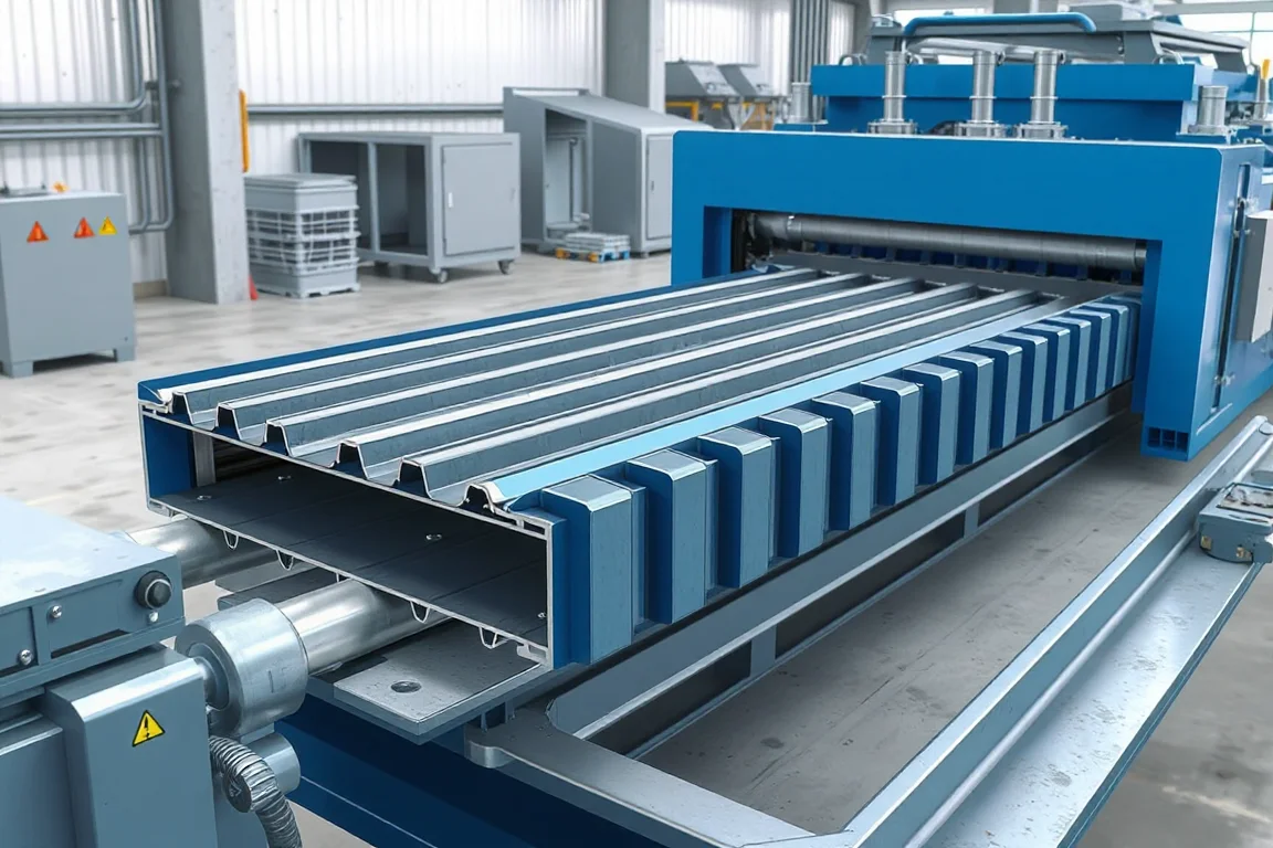
A 1.5 inch roof deck roll forming machine produces a specified structural deck with a nominal 38.1 mm depth. Depth alone does not identify the profile. Rib width, pitch, web shape and side laps distinguish different shallow roof-deck products, so a buyer must select the complete section before machinery can be compared.
This enquiry is broader than B deck. A B-type wide-rib profile is one familiar member of the nominal 1.5-inch family, but other rib arrangements can share the depth. The machine specification should therefore name the actual controlled drawing rather than treating all shallow decks as one product.
Which 1.5-inch section will be manufactured?
Define crest and valley widths, rib pitch, web angles, bend radii and terminal edges. State effective cover and the intended lap construction. Include any optional venting, perforation or other feature in the product definition.
If several profiles share the same nominal depth, list them separately. Common depth does not mean common rolls or cutoff parts. Their different rib arrangements can also require different developed strip widths.
How should the roof-deck role be described?
The deck belongs to a specified roof support assembly, with material, attachments and design requirements defined by that system. It is not simply a decorative roof sheet. Manufacturing acceptance should demonstrate the approved geometry and material.
Do not transfer another producer's load tables or certifications to newly formed deck. The equipment trial and the structural product's qualification serve different purposes and need clear responsibilities in the project plan.
What should the tooling package show?
- The full repeating rib and web geometry.
- Both terminal edges before and after joining.
- Overall width, cover and input-strip requirement.
- Material grade, thickness and finish combinations.
- Required lengths and end condition.
- Special features and their registration.
Use approved samples where matching existing deck is necessary. Compare the lap and accessories as well as the middle ribs, because a visually close section may still fail to join the intended product.
How does the line make the deck?
Coil handling and entry preparation feed strip through progressive tools that develop the ribs and side laps. Required feature operations are integrated at the agreed points. The cutoff then produces lengths for supported transfer and stacking.
Ask whether cutting occurs before or after forming and how the proposed arrangement handles the shortest and longest products. The choice should be explained against the actual section and order mix, not presented as universally best.
How should material variants be trialed?
Pair steel grade, base-metal thickness, coating and strip width. A nominal depth does not establish a material envelope. Select representative combinations, including the demanding cases in the approved product matrix.
Inspect bends, cut edges and feature areas using production-intent material. Retain coil identification with the dimensional records. This gives later production a stable comparison when material supply changes.
What side-lap checks are required?
Use the intended nested or interlocking arrangement and any relevant joining-tool reference. Assemble several sheets and measure effective cover. The trial should not rely on forcing edges into a position that hides an inconsistent formed shape.
Check laps near cut ends and farther along the sheet. Local cutoff distortion can prevent joining even when the interior profile is correct. Keep these observations separate from general rib measurements.
How should multiple shallow profiles share a line?
Request a configuration matrix listing common and exchanged rolls, guides, feature tools and cutoff parts. A shared nominal depth may simplify some aspects of a proposal, but it does not prove a quick or tool-free change.
Measure the transition to the first accepted sheet and joined lap. Include inspection, startup material and downstream adjustments. Compare that result with the actual frequency of profile changes in the order book. Keep sample and program identities distinct for each shallow profile so operators do not release one rib pattern under another product's familiar depth label.
What should the production trial demonstrate?
- Confirm the exact 1.5-inch profile and material.
- Measure ribs, webs, cover and terminal edges.
- Inspect features and cut ends.
- Join sheets using the specified side lap.
- Demonstrate short and long lengths with normal handling.
- Check package condition and profile-change recovery.
- Record accepted output and rejected-start causes.
Use accepted deck orders rather than strip speed alone. Cutting, features and stack removal can determine the practical result, particularly where one line serves several shallow profiles.
Frequently asked questions
Is every 1.5-inch roof deck B deck?
No. The depth can be shared by different rib arrangements. Confirm the exact cross-section and lap rather than using nominal depth as the product identity.
Does 1.5 inches mean 38 mm exactly?
It equals 38.1 mm. Follow the actual drawing and tolerance, and do not treat nominal metric and imperial descriptions as proof of profile compatibility.
Can one cutoff serve every shallow deck?
Only if it is designed and approved for those sections. Different ribs and laps may need different support or cutting components even at the same depth.
Are vented versions included automatically?
No. Define the vent pattern, position and required equipment separately. The complete featured product should be represented in acceptance.
What is the most useful quotation input?
A full section and material matrix with laps, lengths and optional features. Include all shallow profiles planned for the line and the expected frequency of changes.
Choose by complete profile, not depth alone
A 1.5-inch roof-deck line should be matched to the actual ribs, side laps and materials the business will sell. That makes tooling scope and acceptance clear and avoids treating a dimensional family as one interchangeable product.

Continue your research
- Floor Deck Roll Forming Machines
- Floor Deck Roll Forming Machine
- Roof Deck Roll Forming Machine
- B Deck Roll Forming Machine
- N Deck Roll Forming Machine
- H Deck Roll Forming Machine
- How Floor deck roll forming machine Works
- How To Choose a Floor deck roll forming machine
- Floor deck roll forming machine Price: What Affects the Cost?
Configuration & specification inputs
Match the configuration to your section drawing, material and production requirements.
| Parameter | Requirement / confirmation needed |
|---|---|
| Profile geometry | Selected nominal 38.1 mm roof-deck family with complete ribs, webs and terminal-lap drawing. |
| Material | Specified structural-deck steel grade and finish for each shallow-profile variant. |
| Thickness & grade | Approved base-metal thickness combinations paired with grade, strip width and profile. |
| Process route | Coil entry, required features, shallow-deck forming, lap completion, cutting and stacking. |
| Cutting | Ordered lengths with profile-specific support and preserved terminal geometry. |
| Output | Accepted shallow-deck orders including feature operations and meaningful profile changes. |
| Electrical supply | Utilities for the agreed forming, punching, cutting and discharge arrangement. |
| Acceptance | Exact profile identity, ribs, laps, cover, featured areas, cut ends and package condition. |