
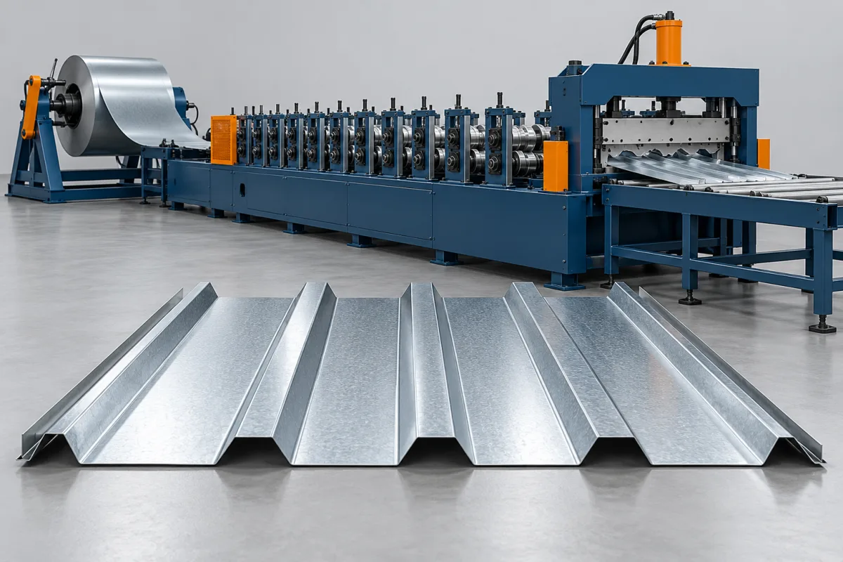
A trapezoidal roof sheet roll forming machine produces panels with angular raised ribs separated by flatter pans. Rib geometry, smaller reinforcing features and the two terminal laps define the product that the machine must reproduce. The useful specification connects those dimensions to material, effective cover, cut lengths and the way sheets are discharged and assembled.
Trapezoidal roofing is a broad family rather than a single standardized section. Two panels with similar overall width can differ in rib pitch, top width, depth, pan features or edge support. Begin with the actual cross-section before comparing tools, automation or a manufacturer's nominal machine range.
What defines the trapezoidal profile?
The principal ribs contain angled or defined sidewalls and a top surface, with pans between them. Some products also include smaller ribs or other features within the pan. The full drawing determines how the strip is developed through the forming stages and which surfaces need support during cutting.
The edge ribs may have different duties from the repeating central ribs. An overlap and underlap must work together, and a return or bearing detail can change the tooling requirement. Inspecting only a central rib does not establish that the finished roofing sheets will assemble correctly.
Which product variations should be separated?
Different rib patterns
Pitch, depth, top width and pan geometry define distinct sections. A line intended for several patterns needs the tools and arrangement to produce each. Similar panel width does not establish that one set of rolls covers the full catalogue.
Different terminal laps
A change at the sheet edge can alter compatibility even when the central pattern stays the same. Show both edges and the assembled relationship. Include the mating reference when a new product must fit an existing supply.
Different material or finish combinations
List these with the corresponding sections, rather than treating material as an independent option. The proposed operating envelope and trial should cover the actual combinations needed by the business.
What should the equipment drawing package contain?
Use a controlled cross-section with clear dimensions and identification of the exposed face. State the distinction between overall width and installed cover. If the panel includes small pan ribs, show their geometry rather than leaving them as a visual suggestion in a photograph.
- Main rib pitch, depth, top width and sidewall geometry.
- Pan width and any specified reinforcing features.
- Overlap, underlap and terminal-edge details.
- Effective cover and its assembly reference.
- Material grade or alloy, thickness convention and finish.
- Required lengths, cut quality and handling criteria.
Where a trade name or local profile number is used, attach the drawing it identifies. Do not assume every supplier interprets that label as the same set of dimensions.
How does the line form ribs and pans?
- Coil preparation: establish the input material, loading arrangement and surface orientation.
- Strip entry: guide the strip consistently into the forming path and include any specified preparation.
- Section development: progressively form the ribs, pans and required smaller features.
- Edge formation: complete the laps and any associated support returns.
- Length cutting: cut the sheet with a method suited to the formed section.
- Supported discharge: move, inspect and stack the product without unacceptable deformation or marking.
Review the actual proposed layout rather than assuming one operation order applies to every line. Any added process, such as a surface treatment or separate panel shaping, should have a defined scope and acceptance requirement.
How are coil width and saleable coverage established?
The incoming strip is developed into the ribbed cross-section. Its width therefore differs from the horizontal overall panel width, while effective cover also accounts for the overlap. Obtain the strip requirement for the approved section instead of adding an arbitrary allowance to the advertised cover.
For order planning, use accepted panel length and effective cover. If a sample order contains sheets of several lengths, calculate their accepted total length before applying the relevant cover width. Do not count setup rejects or damaged panels as saleable area.
Keep this production measure distinct from the installation takeoff. Building geometry, openings, cutting allowances and project-specific details can change the quantity needed on a roof without changing the machine's formed section.
What material range should the line demonstrate?
Specify grade or alloy, thickness, strip width and coating as combinations. The forming and cutting requirements of a wide, stronger material are not established by a successful trial of a narrower, easier product. Identify representative and demanding combinations in the acceptance plan.
Use the intended painted or otherwise finished material when appearance matters. Examine bends, pan surfaces and cut ends after normal handling. A trial in another surface condition cannot establish the complete finish result for the production coil.
If a backing or protective layer is required, include it in the process review. Record the material identity and relevant layer condition with the approved samples so later changes can be assessed against a known reference.
How should single-profile and multi-profile equipment be compared?
A dedicated line focuses on one established pattern and may suit a stable order book. A changeable arrangement can serve more profiles but requires a clear schedule of tools and setup work. Compare those alternatives against the actual frequency and size of orders.
For every transition, identify roll changes, entry work, cutting components and discharge supports. Include first-off measurements and assembled-lap checks in the changeover timing. A tool swap that produces an unaccepted first batch has not yet recovered production.
If a dual-level arrangement is proposed, ask which drive, feeding, cutting and takeoff functions are shared. Two forming paths do not by themselves establish simultaneous output. Assess floor-space savings alongside the complete operating sequence.
Why do cutoff and stacking deserve separate review?
The ribs need suitable support at the cutting and discharge stages. Inspect ends for local deformation and compare the product immediately after cutting with its condition in the stack. This helps separate tooling or cutting issues from later handling damage.
Use both short and long representative lengths in the layout review. Short sheets can require rapid repeated handling, while long panels need a supported path and enough room to move safely. The agreed package format and surface separation should match the finished order.
A faster forming section is not a useful improvement if the receiving equipment cannot handle its output without damage. Consider the whole route when discussing automation and sustained production.
What should an equipment quotation and output trial include?
Issue the same section drawings, material matrix and order schedule to each supplier. Include required profile tools, coil handling, cutting, discharge and any optional operations. Identify commissioning, training and inspection responsibilities rather than leaving them inside an undefined complete-line description.
For output, measure accepted sheets over a stated period with the real length mix. Document coil changes, cutting delays, profile transitions and stack removal according to the agreed trial boundary. Report rejected material separately.
Ask what future geometry changes would require. A different rib pattern, another lap or a larger material envelope may involve new tools or equipment. That distinction is more useful for planning than a broad promise to make roofing sheets of many kinds.
What does acceptance look like for a trapezoidal sheet?
- Confirm the profile revision and production material.
- Measure main ribs, pan features and terminal edges after cutoff.
- Assemble neighboring sheets and verify lap fit and cover.
- Inspect coating, pan appearance and cut-end condition.
- Assess agreed straightness on suitable supports.
- Demonstrate normal takeoff and stacking with representative lengths.
- Recover accepted sheets after required setup changes.
Retain approved samples and a record of their material and inspection conditions. They provide a practical reference for repeat production and help distinguish actual product changes from differences in how a sheet is viewed or supported.
Frequently asked questions
Are all trapezoidal roof profiles interchangeable?
No. Rib geometry, pan details and laps differ. Use the actual drawings and mating samples. A common overall width or similar photograph does not establish that sheets will overlap correctly.
Can one set of rolls change the rib pitch?
That depends on a specifically designed tooling arrangement. Do not assume a width or length adjustment changes fixed section geometry. Ask which target profiles require another set of rolls or a separate path.
Does overall panel width equal roof coverage?
Not generally. Effective cover accounts for the assembled lap. Use the approved installed dimension when calculating nominal coverage, and keep it separate from incoming strip width and the building's final takeoff.
Can the same profile be used for walls?
Use the product-system requirements for the intended application. Similar geometry may appear in roof and wall products, but the machine category does not establish installation suitability. Supply the required application and section details for review.
Does a deeper rib automatically increase the machine's output?
No. Output depends on the complete process and order conditions. Rib geometry changes tooling and support requirements; it is not a production-rate measure. Compare accepted sheets under defined trial conditions.
What makes a quotation request complete?
Provide the full cross-section, material combinations, lengths, lap references and finish criteria. Add the required profile variants and typical orders. These inputs establish what tools, handling and acceptance work are needed.
Connect the rib drawing to an assembled roofing product
Evaluate a trapezoidal line through its complete result: the repeated pattern, terminal laps, material condition and finished handling. A clear drawing and representative trial make the differences between equipment packages visible. That is a stronger basis for selection than profile labels or peak running speed alone.

Continue your research
- Roofing Sheet Roll Forming Machines
- Corrugated Roof Sheet Roll Forming Machine
- IBR Roof Sheet Roll Forming Machine
- R Panel Roll Forming Machine
- PBR Panel Roll Forming Machine
- IBR 686 Roofing Sheet Machine
- How Roofing sheet roll forming machine Works
- How To Choose a Roofing sheet roll forming machine
- Roofing sheet roll forming machine Price: What Affects the Cost?
Configuration & specification inputs
Match the configuration to your section drawing, material and production requirements.
| Parameter | Requirement / confirmation needed |
|---|---|
| Profile geometry | A trapezoidal panel combines flat pans with raised ribs. State which face is exposed and which edge overlaps. Include the pan width and any stiffening ribs in the approval drawing rather than describing only the overall panel width. |
| Material | Galvanized or coated steel; aluminum only after a separate tooling review |
| Thickness & grade | Buyer to specify base-metal thickness and grade; operating range requires supplier verification. |
| Process route | Coil payoff → entry guiding → progressive forming → profile-matched cutoff → supported stacking |
| Cutting | Confirm profile-supported cutoff, cut lengths, end quality and any secondary operations. |
| Output | Define accepted output per shift with the actual profile and material. |
| Electrical supply | Buyer to state voltage / frequency / phase. Installed power requires a confirmed equipment schedule. |
| Acceptance | A machine for one established profile can be compared against a multi-profile arrangement using the actual order mix. Include roll changes, entry adjustments, cutoff tooling and trial sheets. Ask which items are common between profiles and which must be purchased or stored separately. |