
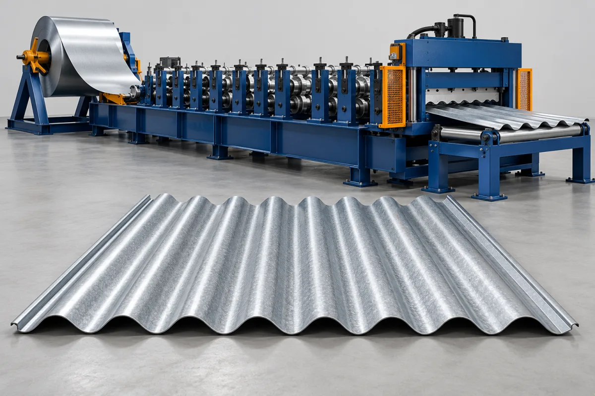
A corrugated roof sheet roll forming machine turns metal coil into sheets with a repeating rounded-wave cross-section. The central waves, terminal edges and side-lap arrangement together define the finished roofing product. Selecting the line means specifying that complete profile and the material and lengths to be supplied, rather than choosing equipment from the word corrugated alone.
The production objective is a sheet that retains the required wave geometry after cutting, overlaps the intended adjacent sheet and reaches the customer without unacceptable finish or handling damage. Wave pitch, depth, effective cover and material development connect the roof product to its roll tools and coil requirements.
What distinguishes a corrugated sheet from other roofing profiles?
Corrugated roofing has repeated curved waves, unlike a trapezoidal sheet's more angular ribs and broad pans. That difference changes the forming geometry and the way the sheet edges nest. Tools designed for one shape should not be assumed to make the other through a simple width adjustment.
The word corrugated also covers different wave sizes and edge arrangements. Obtain the actual product drawing, including both terminal edges. A photograph may communicate the general pattern while concealing the details that determine whether new sheets match an existing roof or another supplier's product.
Which corrugated product is the machine expected to make?
One established wave pattern
A dedicated line can be evaluated around a stable section, with order changes mainly involving length, color or material combinations. Define the accepted geometry and laps before discussing running speed. The same profile name can still refer to different local drawing conventions.
Several corrugation sizes
Changes to wave pitch, depth or edge geometry can require different forming tools. Ask how each requested pattern is produced and what must change between them. A cut-length controller does not provide a new wave cross-section.
Corrugated and other roofing profiles
If the product range also includes trapezoidal sheets or another section, identify a separate tool set or forming path. Compare a multi-profile proposal against dedicated lines using the actual order mix and the complete changeover and handling requirements.
What should the corrugation drawing specify?
Wave depth and pitch describe the repeating pattern, but they do not fully define the sheet. The number of waves, edge conditions, bend shapes and lap arrangement establish overall width and useful coverage. Those dimensions need a coherent reference rather than a collection of unrelated nominal figures.
- Wave pitch, depth and the specified curve geometry.
- The number and arrangement of complete or partial waves.
- Both terminal edges and the intended overlap.
- Overall sheet width and effective cover after assembly.
- Required lengths and cut-end condition.
- Material combinations and surface acceptance.
Where compatibility with existing sheets matters, provide representative mating samples. Inspecting only the center waves can miss an edge difference that prevents the complete roofing product from fitting.
How is the wave profile formed?
- Coil payoff: present the specified strip safely and with the correct visible-face orientation.
- Guided entry: establish alignment and any required preparation before the forming path.
- Progressive wave development: form the repeated curves through successive roll stages.
- Edge completion: reproduce the terminal waves and lap geometry required by the drawing.
- Length cutting: produce the requested sheets with suitable support at the cut.
- Discharge and stacking: preserve the section and finish through handling and packing.
The proposed machine layout should show the actual sequence and where measurements are taken. If an additional operation such as curving or another feature is required, define it separately rather than assuming it is part of a straight-sheet former.
How are strip width and effective cover related?
The incoming strip supplies the material developed into the corrugations. The resulting overall sheet width differs from the flat development, while the effective cover also accounts for the side lap. These are different quantities and should be confirmed for the approved geometry and forming process.
For a clearly stated planning example, 120 accepted sheets with a 2.5-metre length and 0.8-metre effective cover represent 240 square metres of nominal panel coverage. Those assumed dimensions are not machine specifications or a roof-design recommendation. Building takeoffs also need their own allowances for openings, cuts and installation details.
Use the supplier-confirmed strip requirement when arranging coil supply. A fixed allowance added to useful coverage is not a reliable substitute for the development of the actual waves and edge conditions.
What material and finish requirements should be reviewed?
Specify grade or alloy, base-metal thickness, coating and any protective layer. Pair those requirements with the intended width and profile. Separate maximum values do not prove that every combination is within the proposed line's operating envelope.
Inspect the wave crests, valleys and cut ends using production-intent material. A coated sheet should be assessed for the required surface condition after forming and handling. An attractive sample in another material cannot establish the complete result for the intended coil.
Identify the exposed face and trace its contacts through guides, rolls, supports and stacking. Surface damage can be introduced after the forming stage, so protected handling belongs in the equipment discussion.
Which cutting and discharge choices matter?
The cutting arrangement needs to suit the wave section and required lengths. Ask how the sheet is supported and how the process avoids unacceptable end distortion. Inspect the completed cut rather than judging quality while the strip remains constrained within the line.
Discharge should accommodate both short and long orders. Frequent short sheets can increase handling activity; long sheets need appropriate support and a clear path to the stack. Include the intended package format and any surface separation in the layout review.
Do not assume that a faster forming section increases delivered output if the takeoff area cannot receive the sheets. The complete route must keep pace while preserving the product.
How should profile changeover be evaluated?
List what changes for each requested corrugation: roll tools, guides, cutting components and supports. Distinguish a different wave pattern from a routine change in cut length. Material changes may also require their own reviewed setup and inspection.
Time the transition through to accepted sheets and a satisfactory overlap check. Include setup material and any correction before normal production resumes. A tool exchange alone does not establish first-good-sheet recovery.
If repeat orders are common, demonstrate returning to an earlier profile. Keep the approved sample and setup reference identified by drawing and material so the recovered product can be assessed consistently.
What explains cost and output differences between proposals?
Compare the same profile drawings, material combinations and finished lengths. Required tool sets, coil handling, cutting, stacking and optional operations can explain major differences in scope. A former-only quotation is not equivalent to a package that also delivers a complete supported handling route.
Measure accepted sheets over a representative order and state which delays are included. Record rejected starts, damaged output and changeovers. Useful coverage can then be calculated from accepted length and the actual effective cover, rather than treating all processed strip as saleable roofing.
Separate future profiles from the initial requirement. Ask what can be added with tools and what needs another equipment arrangement. That distinction makes expansion costs clearer than a broad claim of multi-profile capability.
What should a corrugated-sheet trial prove?
- Verify the material and approved wave drawing.
- Measure repeated geometry and both sheet edges after cutting.
- Assemble adjoining sheets to check nesting and effective cover.
- Inspect wave crests, valleys and cut ends for unacceptable surface damage.
- Review straightness in the agreed support condition.
- Demonstrate representative lengths and normal stacking.
- Recover accepted output after any required changeover.
Keep observations from the machine exit and the completed stack distinct. That helps determine whether a deviation arises during forming, cutting or handling rather than treating every problem as the same roll-setting issue.
Frequently asked questions
Can the same tools make trapezoidal roofing?
Rounded waves and angular ribs require different section development. A line needs the specified tooling or separate path for the second product. Do not infer that capability from the general roofing-machine description.
Does a corrugated profile name guarantee compatibility?
No. Wave dimensions and terminal laps may differ. Use the actual drawing and mating samples, especially when replacing or extending an existing supply. The edge assembly is as important as the central appearance.
Can the former also curve finished roofing sheets?
Only if the specified equipment and process include that operation. Straight roll forming and the additional shaping of panels are separate requirements. Provide the intended curved product and its acceptance criteria for review.
Should output be quoted in sheets or square metres?
Either can be useful if the lengths, effective cover and accepted quantity are stated. The same sheet count can represent different coverage for different products. Keep the calculation transparent and distinguish it from a building's final installed area.
Why inspect several sheets together?
An assembled group shows nesting, lap fit and accumulated coverage that one sheet cannot demonstrate. It also helps reveal whether the terminal waves match the intended product rather than merely resembling the center pattern.
What should a buyer supply first?
Provide the complete wave drawing, material combinations, length schedule, finish requirement and expected order mix. Include mating samples where compatibility matters. Those inputs define a meaningful forming and acceptance target.
Specify the waves, edges and delivered sheet together
A corrugated line is best evaluated against the whole roofing product: its repeated geometry, overlap, material and finished handling condition. Connect those requirements to tools and the complete production route. That makes a quotation comparison more useful than choosing by profile name or peak strip speed alone.

Continue your research
- Roofing Sheet Roll Forming Machines
- Trapezoidal Roof Sheet Roll Forming Machine
- IBR Roof Sheet Roll Forming Machine
- R Panel Roll Forming Machine
- PBR Panel Roll Forming Machine
- IBR 686 Roofing Sheet Machine
- How Roofing sheet roll forming machine Works
- How To Choose a Roofing sheet roll forming machine
- Roofing sheet roll forming machine Price: What Affects the Cost?
Configuration & specification inputs
Match the configuration to your section drawing, material and production requirements.
| Parameter | Requirement / confirmation needed |
|---|---|
| Profile geometry | For a corrugated sheet, measure the repeating wave and define the edge condition at both laps. Check nesting with another finished sheet; a visually similar sinusoidal wave can still produce a poor lap if its pitch or terminal bend differs. |
| Material | Galvanized or coated steel; aluminum only after a separate tooling review |
| Thickness & grade | Buyer to specify base-metal thickness and grade; operating range requires supplier verification. |
| Process route | Coil payoff → entry guiding → progressive forming → profile-matched cutoff → supported stacking |
| Cutting | Confirm profile-supported cutoff, cut lengths, end quality and any secondary operations. |
| Output | Define accepted output per shift with the actual profile and material. |
| Electrical supply | Buyer to state voltage / frequency / phase. Installed power requires a confirmed equipment schedule. |
| Acceptance | Examine the exposed face for marks, the wave crests for coating damage and the cut end for distortion. Compare samples from the beginning and end of a run. Keep the profile inspection separate from roof installation requirements such as fixings, support spacing and weathering details. |