
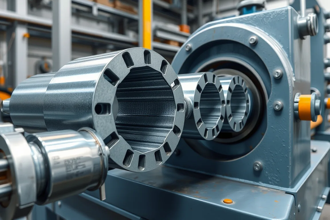
Greenhouse roll forming machines are often described by the number of forming stations they contain. That number alone reveals little about whether the machine can produce a drainage gutter, film-lock channel, or structural member that fits the greenhouse. The roller tooling design — the sequence of shaped rolls, the way the strip is guided, the placement of punches, and the cutoff arrangement — is what turns a coil of protected metal into a usable component. This guide explains how that design is developed and how to evaluate it, without treating any particular roll count as evidence of quality.
What a greenhouse roll forming machine actually has to produce
A greenhouse uses several profiles that serve unrelated functions. A drainage gutter is an open section that must shed water and join to downpipes or adjacent gutters. A film-lock channel is a narrow, often re-entrant shape that grips a retaining element, such as a wire or spring, without tearing the covering. A support section may be a structural post, a truss chord, or a crop-support rail with holes for trellis wire or brackets. Connection holes — for bolts, self-tapping screws, or clips — are located to match the greenhouse drawing.
These profiles differ in material thickness, bend severity, hole placement, and end use. A single machine may be intended to run more than one of them, but the roller tooling must be designed for each profile individually. A gutter section and a film-lock channel do not share the same forming strategy simply because they are both made from coil.
From functional geometry to a forming sequence
Tooling design starts with the finished section drawing, not with a preferred number of stations. The designer identifies every functional surface: the drainage floor and walls, the film-retention groove, the mating faces that bolt to a post, and the hole pattern. These surfaces become the datum references for the strip as it passes through the line.
The forming sequence then develops those bends gradually. Early stations make shallow bends in the central web or at the edges, depending on which part of the section must remain flat for guiding. Later stations close the section, form the re-entrant groove or the gutter lip, and prepare the strip for the cutoff. The order matters because a bend formed too early can prevent the strip from being located accurately in a later station.
The sequence also determines where the strip is driven and where it is merely guided. If drive rolls grip a surface that later becomes a visible or sealing face, they can mark it. If the strip is guided only by its edges, those edges must be consistent from the coil. The tooling design should state which surfaces locate the strip and which surfaces are allowed to slide.
How punch and cutoff tooling share the forming line
Connection holes are usually punched after some forming has occurred, because the strip is flatter and more stable before severe bends are introduced. In some layouts, punching is placed before the first forming station; in others, it sits partway down the line where the web is still accessible. The choice affects hole position accuracy, die access, and scrap removal.
The cutoff follows the last forming station. It must cut the finished section without collapsing the gutter walls or deforming the film-lock groove. The cutoff tooling therefore has to support the profile internally or externally at the cut plane. If the section is closed, the cutoff may need an mandrel or a shaped blade that enters the open side. The design should define the cut length, the end condition, and any secondary operation, such as deburring or punching a notch after cut.
Punch and cutoff tooling are not accessories added after the roll tools are designed. They interact with the forming sequence: a hole punched early may distort in a later bend, and a cutoff that grips the profile in the wrong place may pull the strip out of alignment. Reviewing them together is part of tooling design, not a separate purchasing task.
Material behaviour and springback in roller tooling design
Protected metal sections — steel or aluminium with a coating or finish — behave differently from bare strip. The coating can affect friction, galling, and the amount of springback after a bend. Springback is the elastic recovery of the material as it leaves the roll gap; it means the finished angle is slightly more open than the roll shape. Tooling design addresses springback by over-bending slightly, by using a final sizing station, or by combining both.
The design should account for material variation. Coil from different suppliers, or even different batches, can vary in yield strength and thickness. A forming sequence that works only for one narrow condition may need frequent adjustment when the coil changes. The tooling design should identify which stations are sensitive to thickness and how the setup is adjusted — for example, by shimming a roll, changing a spacer, or repositioning a guide. The buyer should specify the base-metal thickness and grade; the operating range requires supplier verification.
Locating the strip and avoiding marking
Every roll station has a locating function. Some rolls contact the strip across its full width to drive it; others contact only the edges to guide it. If the locating surfaces are not consistent, the strip wanders, and bends drift from the intended position. This shows up as a profile that is twisted, a hole pattern that is off-centre, or a film-lock groove that varies in width.
Marking is a related concern. Drive rolls that contact a visible surface can leave impressions, especially on coated material. The tooling design can reduce marking by using larger roll diameters, lower contact pressure, or by driving on a surface that will be hidden in the assembled greenhouse. The design should state which surfaces are cosmetic and how they are protected.
Comparing tooling design alternatives
Two suppliers may offer the same number of forming stations but very different tooling strategies. One may use a simple sequence of identical roll pairs; another may use a mix of driven and idler stations, with separate guide rolls and a final calibration pass. The tradeoffs are not about station count alone.
- Simple sequence: easier to set up, but may struggle with re-entrant shapes or tight bends, and may require more manual adjustment when material changes.
- Progressive sequence with guide rolls: more stations and more setup points, but better control of strip location and bend development; requires documented setup so production does not depend on an undocumented adjustment.
- Separate punch and cutoff modules: allows independent timing and easier maintenance, but adds length and cost to the line.
- Combined punch and cutoff: compact, but any change to hole pattern or cut length affects the same tooling assembly.
- Hardened versus non-hardened rolls: hardened rolls resist wear on abrasive coated material, but cost more and may be less forgiving if the setup is wrong.
The right choice depends on the profile, the material, and the expected production life. A design that is easy to adjust may suit a line that runs several profiles; a design optimized for one profile may suit a dedicated line.
Production setup, tool identification and changeover
Roller tooling design includes the setup documentation. Each roll station should be identified, and the accepted setup — shim thickness, roll gap, guide position — should be recorded. If production depends on an undocumented adjustment made by an operator, the machine will drift when that operator is absent or when a new coil arrives. Tool identification also matters during changeover: if two profiles share the same line, the correct rolls, spacers, and punch dies must be traceable.
Changeover time is a design consideration. Quick-release roll assemblies, keyed shafts, and colour-coded spacers can reduce the time to switch profiles. But these features add cost and complexity. The buyer should decide how often the line will change profiles and whether the tooling design supports that frequency without constant re-adjustment.
Component production versus assembly and in-service performance
A roll forming line produces components: gutters, channels, posts. It does not assemble them into a greenhouse, and it does not certify that they will perform in service. The tooling design can ensure that the connection holes match the drawing and that the film-lock channel accepts its retaining element, but the fit with the covering, the drainage joint, and the structural capacity are separate evaluations.
For growing systems, the nutrient and cleaning environment is another boundary. A metal channel called hydroponic is not automatically suitable for contact with nutrient solution. Material and coating suitability need specialist confirmation. The roll forming machine may produce the shape accurately, but the material choice and post-treatment determine whether it belongs in that environment.
Acceptance checks for roller tooling design
Acceptance should be based on the actual profile and material, not on a generic output rating. The following checklist covers the design and production interface.
- Identify every functional dimension and its mating part: gutter joint, film-retaining hardware, connection holes, support brackets.
- Confirm the base-metal thickness and grade; verify the operating range with the supplier.
- Review the forming sequence: how bends develop, which surfaces locate the strip, how springback is addressed.
- Check punch and cutoff tooling together with the roll tools; confirm hole position after forming and cut end quality.
- Verify tool changes using the agreed material and profile extremes.
- Confirm the cutoff is supported by the profile and that cut lengths match the greenhouse drawing.
- Record the accepted setup and tool identification so production does not depend on an undocumented adjustment.
- Check film-retaining hardware fit, drainage joints, and connection holes against the greenhouse drawing.
- For growing systems, evaluate material and coating suitability for the actual nutrient and cleaning environment.
FAQ
Does a higher number of forming stations mean better roller tooling design?
No. Station count is a result of the forming sequence, not a measure of quality. A simple profile with shallow bends may need only a few stations; a complex film-lock channel with a re-entrant groove may need more. What matters is whether the sequence locates the strip, develops each bend without distortion, and accounts for springback and material variation. A roll count without a forming design does not demonstrate quality.
How is a drainage gutter different from a structural post in tooling design?
A gutter is an open section with a drainage floor and joints that must shed water. Its tooling must form the open shape without closing it, and the cutoff must not collapse the walls. A structural post is often a closed or semi-closed section with bolt holes; its tooling must control twist and hole alignment over a longer length. They require different forming sequences and different cutoff support.
Can the same roll forming line produce both a film-lock channel and a support section?
Sometimes, if the material thickness and section width are compatible and the tooling is designed for changeover. But a film-lock channel has a narrow, re-entrant groove that needs precise roll shapes, while a support section may have a larger open profile. The changeover must include the correct rolls, guides, punch dies, and cutoff tooling. The design should document the changeover procedure and verify it at the profile extremes.
What causes a film-lock channel to vary in width after forming?
Variation can come from strip location, springback, or material thickness changes. If the strip is not guided consistently, the groove will shift. If springback is not addressed, the groove may open. If the coil thickness varies, the roll gap may need adjustment. Diagnostic evidence includes measuring the groove width at several points along a run and comparing it with the strip position at the entry. The fix may be a guide adjustment or a sizing station, but it should be based on measurement, not trial and error.
How should punch and cutoff tooling be reviewed during selection?
Review them together with the roll tools. Ask how the punch die is positioned relative to the forming stations, whether the strip is flat enough at the punch point, and how the cutoff supports the finished section. Confirm that hole position is checked after forming, not just at the punch. Confirm that cut lengths and end quality match the greenhouse drawing. If a secondary operation is needed, such as deburring, it should be defined in the design.
What documentation should come with the roller tooling design?
The design should include a forming sequence drawing, roll identification, setup specifications such as shim thickness and roll gap, punch and cutoff tooling drawings, and a changeover procedure if more than one profile is run. The accepted setup should be recorded so production does not depend on an undocumented adjustment. Tool identification should allow the correct rolls to be traced to the correct profile.
Continue your research
- Greenhouse Profile Roll Forming Machines
- Greenhouse Gutter Roll Forming Machine
- Greenhouse Channel Roll Forming Machine
- Greenhouse Film Locking Channel Machine
- Greenhouse Crop Support Channel Machine
- Greenhouse Purlin Roll Forming Machine
- How Greenhouse roll forming machine Works
- How To Choose a Greenhouse roll forming machine
- Greenhouse roll forming machine Price: What Affects the Cost?