
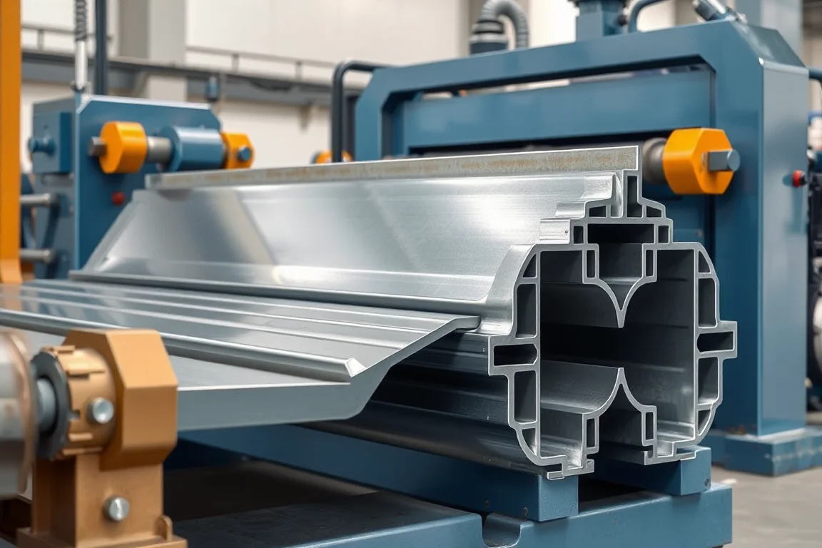
Floor deck tooling must create the approved rib geometry, bearing surfaces, terminal laps and specified functional features. A visually similar deep profile is not necessarily an equivalent deck. Tool development and acceptance should remain tied to a controlled product drawing and material matrix.
Use a complete section and feature definition
Provide rib depth, pitch, flats, slopes, bend details and both side edges. Distinguish overall width from effective cover. Add embossment or other feature drawings where they are part of the product.
A nominal depth or commercial profile name cannot replace these inputs. The tool set must reproduce the exact geometry selected for the deck system, not a generic approximation of a familiar section.
Review progressive development through the ribs
The strip is shaped through successive intermediate forms. The distribution of forming work matters to the final section and material path. Ask the tool designer to explain the proposed development and the important boundary combinations.
Do not rank proposals by station count alone. The relevant evidence is consistent complete-sheet geometry in the required materials. Different tooling concepts can use different arrangements to achieve an accepted product.
Keep functional embossments within the approved design
Where surface features contribute to the specified deck product, their shape and placement require controlled tools and inspection. They are not arbitrary texture that can be changed for convenience.
Identify how the feature operation interacts with the forming sequence. Inspect the final sheet rather than only a separate feature sample. Manufacturing conformity to the drawing remains distinct from the structural performance evidence of the deck system.
Develop the two side edges deliberately
The overlap and receiving edge may have different functions. Show adjacent sheets in their intended relationship and identify the cover reference. Tooling acceptance should include that assembly, not merely a repeating central rib.
Inspect lap continuity along representative lengths and at cut ends. A good middle coupon can miss a local edge condition that prevents sheets from meeting correctly on a floor layout.
Match the tool envelope to material combinations
Grade, thickness convention, strip width and coating should be specified together. A successful trial on one convenient coil does not establish the entire proposed range. Request the evidence supporting each important required combination.
If material changes, assess the impact on formed geometry and functional features. Preserve the coil identity with trial samples and setup references. This allows later deviations to be investigated without assuming every difference is tool wear.
Coordinate cutoff components with the deep section
The chosen cutting route needs appropriate support for the approved ribs and laps. Review section-specific components and inspect both ends of complete sheets. Length accuracy and local deformation are separate acceptance checks.
A new deck profile may require different cutoff parts even when its depth is unchanged. Include them in the change matrix and spare-part records. Similar-looking tools should not be substituted by guesswork.
Define what profile changes really require
Request a list of tools, guides, feature components and inspection references for each transition. Distinguish adjustment within a designed range from replacement tooling for another section. The term flexible should have a concrete configuration meaning.
Time recovery to the first accepted complete sheet. A fast exchange of the main forming tools may leave other setup and validation work. The business needs repeatable product recovery, not only movement speed.
Validate geometry after normal handling
Inspect the sheet in agreed support conditions and after the intended discharge or nesting route. This distinguishes tooling output from later damage. Retain both local section measurements and complete-sheet observations.
- Verify drawing, material and tool identities.
- Measure ribs, bearing surfaces and side edges.
- Inspect functional surface features.
- Check length and both cut ends.
- Assemble adjacent sheets for lap and cover checks.
- Inspect after stacking and configuration recovery.
Use a small-design-change scenario to expose scope
Define the measurement references for that revised feature before cutting tools are ordered. Decide which surfaces establish the datum, how complete sheets are supported and how adjoining laps are assembled for checking. If acceptance relies on a fixture, document its identity and purpose. Comparing an unconstrained sheet with one forced into a fixture can create an apparent disagreement that is really an inspection-method difference.
Ask the tool supplier to demonstrate return-to-profile recovery after a meaningful change. Run an accepted baseline, change to the second required section, then return to the first with its correct feature and cutoff components. Inspect the complete sheets each time. This sequence tests the tool-identification and setup system as well as the hardware. Record rejected starts and first-good-sheet time because they affect the economic value of flexibility. A fast exchange that requires repeated undocumented corrections may be less useful than a more deliberate transition with a clear, repeatable release process.
Suppose a new deck retains its nominal depth but changes the side lap or embossment arrangement. Ask which forming, feature and cutting tools must change, and what new trials are needed. The unchanged depth does not establish that existing tools can make the revised product.
Keep product approval responsibilities visible during that discussion. A machine supplier can demonstrate dimensional conformity, but the revised deck's performance requires the appropriate product-design evidence. Tooling convenience should not silently redefine the structural product.
Frequently asked deck tooling questions
Can any deep-rib tools make composite deck?
No. The exact section and functional features must match the approved product. A deep rib alone does not establish composite-deck capability or performance.
Is more tooling always better?
Tool quantity alone is not a useful quality measure. Evaluate the development concept, material envelope and accepted complete-sheet results.
Why inspect side laps after cutting?
Cutting and handling can affect the terminal edges locally. Their condition in the middle does not prove usable ends or continuous fit.
What should be retained with delivered tools?
Controlled drawings, material combinations, tool and cutoff identities, setup references and acceptance records. Include the exact features and adjoining-sheet checks used to approve the configuration.
Continue your research
- Floor Deck Roll Forming Machines
- Floor Deck Roll Forming Machine
- Roof Deck Roll Forming Machine
- B Deck Roll Forming Machine
- N Deck Roll Forming Machine
- H Deck Roll Forming Machine
- How Floor deck roll forming machine Works
- How To Choose a Floor deck roll forming machine
- Floor deck roll forming machine Price: What Affects the Cost?