
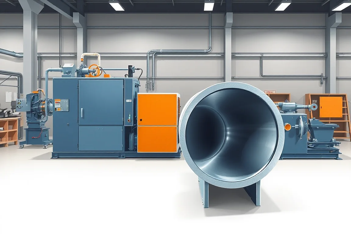
A downspout elbow machine produces the directional fittings used with a specified rainwater downspout system. Its input is commonly a prepared straight section, and its forming method changes that section into the required bend while preserving the connection ends and acceptable wall condition.
This is a different operation from continuously roll forming straight downspout from coil. The two machines can be part of one production project, but their tooling, cycle and acceptance requirements should be evaluated separately. A reliable elbow route begins with a compatible straight-section blank.
Which elbow product is required?
Define the downspout cross-section, bend direction, intended angle and end arrangement. Rectangular products can turn in different planes relative to their broad and narrow faces. A simple elbow name can therefore be ambiguous without a drawing.
Show the fitting in its installed relationship with the straight sections or outlet. This clarifies orientation, end engagement and the dimensions that matter to the intended offset. Do not infer those details from a photograph taken from one direction.
What should the blank specification include?
- Complete straight-section geometry and seam construction.
- Material, thickness and finish.
- Blank length and end condition.
- Seam orientation relative to the bend.
- Required mating-end preparation.
- Permitted final elbow geometry and inspection references.
The elbow machine should be reviewed with the actual blank from the intended upstream route. A sample from another downspout system can differ in corners, seam or material response even when its nominal size matches.
How does elbow forming differ from straight roll forming?
The straight former develops a constant longitudinal section from strip. Elbow equipment changes the direction of an already defined section through its supported forming process. Some arrangements create repeated localized corrugations or folds to develop the bend, while other constructions use different methods.
Ask which method the proposal uses and what input it requires. The equipment should not be assumed to create a smooth-radius fitting, a particular corrugation appearance or every bend direction without the relevant tooling and demonstration.
Keep the two production rates separate. A fast straight-downspout line may supply blanks more quickly than the elbow station can process them, so complete fitting output needs its own capacity study.
What does the production sequence include?
- Confirm the released elbow size, direction and end configuration.
- Prepare and identify the compatible straight-section blank.
- Locate the blank in the specified orientation.
- Apply the machine's controlled forming sequence.
- Complete required end preparation or other secondary work.
- Inspect angle, section condition and mating fit.
- Identify and pack accepted fittings without changing their geometry.
The exact sequence and supports depend on the machine. Review the maker's operating and guarding arrangements rather than treating manual positioning near forming tools as an informal production shortcut.
Why does seam orientation matter?
The longitudinal seam is part of the blank construction and should be included in the forming review. Its position relative to the bend can affect how the completed fitting is assessed and how its walls and connection areas behave during the process.
Specify the required orientation and inspect the seam after forming. Record opening, local distortion or finish damage separately from the bend angle. A fitting that reaches the desired direction can still be unacceptable because another part of the section changed.
If the upstream downspout line changes seam geometry or material, review the elbow process again. The downstream station should not be assumed unaffected by a change to its input product.
How should angle and direction be defined?
Use a drawing with unambiguous reference surfaces and orientation. State whether the bend acts across the wide or narrow face of a rectangular downspout and how the inlet and outlet ends are designated. This prevents apparently identical fittings from turning in the wrong plane.
Measure the finished fitting using an agreed method after release from the tools. A machine setting or displayed value is not the same as the measured product result. Material response and the selected forming method need to be reflected in the acceptance trial.
For offsets using more than one elbow, assemble the intended combination and straight piece. The required offset depends on the complete arrangement, not only on one nominal bend angle.
What material combinations should be trialled?
Specify grade or alloy, thickness and finish for every blank family. Aluminum and coated steel, for example, should not be treated as interchangeable merely because their nominal downspout dimensions match. The tools and process need to suit the actual material response.
Inspect the coating and wall condition around the bend and at the support contacts. A clean straight blank can be marked during elbow forming or handling. Use the intended commercial finish in the trial rather than relying only on uncoated development samples.
Retain blank and finished-fitting references with the material record. They help locate whether a later issue originates upstream or at the elbow station.
How should connection ends be protected?
The inlet and outlet ends must retain the specified relationship with adjoining downspout and fittings. Identify which end is reduced, expanded or otherwise prepared where the system requires it. The forming process should not unintentionally change those mating areas.
Assemble production-intent straight sections with both ends of trial elbows. Check alignment, engagement and the intended overlap without unplanned reshaping. A fitting that connects at one end but not the other is not a complete pass.
If end preparation occurs after bending, include that equipment and its handling constraints. A bent blank is not the same deliverable as a ready-to-connect elbow.
What size flexibility should be demonstrated?
Request a list of supported sections, bend directions and material combinations. Identify the tools or supports required for each and the work involved in changing them. A round fitting and a rectangular fitting should not be assumed to share the same setup.
Demonstrate a relevant size change, produce an accepted fitting and recover the original configuration. Include setup pieces, final measurements and connection checks in the first-good-product time.
Where several angles are required, show the supported range through representative products. Avoid treating a broad control adjustment as proof that every intermediate fitting meets the same dimensional and wall-condition requirements.
How should inspection distinguish different defects?
Check bend geometry, cross-section, seam condition, connection ends and surface finish separately. A correct angle can coexist with an over-distorted wall, while a sound section can be oriented in the wrong plane. A single pass/fail photograph does not explain those differences.
Record the blank, material, orientation and setup when a deviation appears. Compare the straight input with the formed result before changing settings. Physical inspection and correction must follow the equipment maker's safe procedures with the required isolation.
How should output and packing be planned?
Measure accepted ready-to-connect elbows for a stated size, direction and material mix. Include blank preparation, positioning, forming, end work, inspection and packing. The forming stroke alone is not the complete operating cycle.
For planning only, 100 drainage offsets using two specified elbows each require 200 accepted fittings, plus the correct connecting straight sections. Actual quantities and geometry come from the installation layout. Extra fittings of the wrong direction do not complete the order.
Pack so bends and mating ends remain protected. Labels should distinguish section, angle, direction, material and finish. Similar elbows can be difficult to sort once mixed in a carton.
What should quotation and acceptance include?
- Compatible blank and seam specifications.
- Supported section and material combinations.
- Measured bend geometry and correct orientation.
- Wall, seam and finish condition after forming.
- Connection fit at both ends.
- Required tooling changes and recovered production.
- Accepted complete-fitting output and packed condition.
Identify the straight-downspout former and any end-preparation equipment separately. Clear boundaries make it possible to compare a stand-alone elbow station with an integrated fitting-production project fairly.
Frequently asked questions
Does an elbow machine make straight downspout from coil?
Not necessarily. Many arrangements process prepared straight sections. Confirm the required input and separate upstream forming or blank preparation from the elbow operation.
Are all rectangular elbows the same direction?
No. They can turn in different planes relative to the section. Use an oriented drawing and clear part identification rather than relying on a generic elbow label.
Can one tool handle every material?
Only the reviewed combinations should be assumed. Material, thickness, seam and finish affect the process. Trial the actual commercial blanks for each required family.
Does the displayed angle prove the fitting angle?
No. Measure the completed part using the agreed references. The machine setting is part of the process, while the finished geometry is the acceptance result.
Why test both connection ends?
Forming and end preparation can affect them differently. A complete elbow must fit its intended adjoining components at both ends without unplanned modification.
What should an enquiry include?
Provide blank and elbow drawings, seam orientation, materials, finishes, directions, angles and end details. Add quantities and the upstream production plan. This defines a complete fitting-manufacturing requirement.

Continue your research
- Gutter & Downspout Roll Forming Machines
- Gutter Roll Forming Machine
- Downspout Roll Forming Machine
- K Style Gutter Roll Forming Machine
- Half Round Gutter Roll Forming Machine
- Box Gutter Roll Forming Machine
- How Gutter roll forming machine Works
- How To Choose a Gutter roll forming machine
- Gutter roll forming machine Price: What Affects the Cost?
Configuration & specification inputs
Match the configuration to your section drawing, material and production requirements.
| Parameter | Requirement / confirmation needed |
|---|---|
| Profile geometry | Defined elbow section, bend plane and inlet/outlet relationships |
| Material | Actual straight-blank material, thickness, seam and finish |
| Thickness & grade | Approve blank and forming combinations for each elbow family |
| Process route | Blank preparation, controlled orientation, elbow forming, end completion and inspection |
| Cutting | Specify input blank length and finished mating-end preparation separately |
| Output | Accepted complete elbows including blank handling, forming, end work and packing |
| Electrical supply | Confirm supply and utilities for the selected elbow and end-preparation equipment |
| Acceptance | Measure finished bend geometry, inspect seam/walls and test both mating ends with intended sections |