
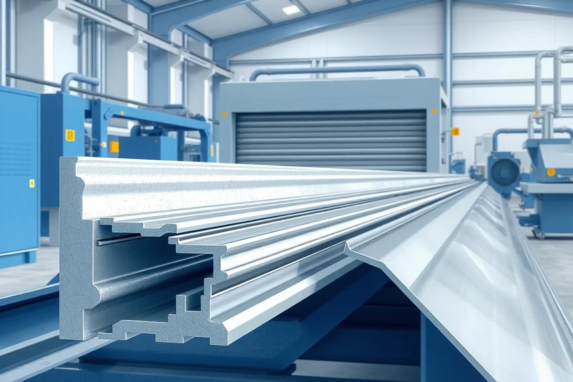
A rolling shutter guide rail roll forming machine produces the side channels that guide the curtain within a specified shutter-door system. The useful geometry includes the receiving opening, internal path, fixing arrangement and any wear-strip, seal or retention features. A generic channel of similar size is not automatically an equivalent guide.
The equipment should be selected around the complete curtain-and-guide interface. Slat ends, end fittings, wind-related retention components and lining materials can all affect the required section. Their actual design must be available before the forming tools are approved.
What does the guide rail need to accommodate?
The guide receives the moving edge of the curtain and connects to the surrounding structure through its defined fixing arrangement. Some products include separate liners, seals or multiple formed components. The profile drawing should show the completed guide assembly rather than only its outer shell.
Identify the intended curtain and end fittings. A rail that works with one slat family may not suit another, even if their visible face widths are similar. Guide compatibility is a system relationship, not a consequence of choosing an oversized opening.
Which dimensions are functional?
- Guide opening and internal receiving path.
- Depth, returns and any retention geometry.
- Wear-strip or seal accommodation.
- Fixing flanges, holes and mounting references.
- Interfaces between separate guide components.
- End, entry and joining details where required.
Use clear datums and specify the condition in which dimensions are measured. A lined guide has a different effective internal relationship from the bare formed shell, so the completed configuration needs its own check.
How does guide production differ from slat production?
The slat is a repeated moving member, while the guide is a longitudinal receiving component with its own mounting and contact surfaces. Their profiles, materials and feature schedules can be very different. A slat former should not be assumed to produce guides without another tooling and process review.
Where a guide is assembled from multiple profiles, identify each part and how it is joined. A line making one guide shell is not a complete guide-assembly route if liners, brackets or mating sections remain to be installed.
What does the manufacturing sequence include?
- Release the correct guide and feature configuration.
- Identify and present the specified coil.
- Produce required fixing or assembly features.
- Develop the channel, returns and liner interfaces progressively.
- Cut and prepare the ends.
- Add specified liners, seals or other components where included.
- Inspect the complete guide and identify accepted lengths.
The order of individual operations depends on the equipment. Ask how the process controls the internal path and preserves it through cutting and collection. Those dimensions matter more than a broad outside-envelope check.
How should material and finish be specified?
List grade or alloy, base-metal thickness, strip width and finishing route for each guide family. The selected material must suit the approved guide design and forming process. Do not assume another material is equivalent because the same outside shape can be produced.
Inspect bends, contact surfaces and cut ends with the actual production finish. Where a liner or seal is fitted, include its attachment and final condition in the trial. The bare metal sample is not always the final acceptance object.
Retain material identity with the guide configuration and inspection record. This supports investigation if a later batch changes shape or becomes difficult to assemble with its specified liner or curtain.
What should liner and seal interfaces prove?
Provide the actual wear-strip, brush, seal or other insert drawing where the design uses one. Identify its retention surfaces and the intended installation method. A nominal groove width alone may not describe whether the component stays correctly positioned.
Install representative inserts in production-length guides and inspect their continuity and seating. Check near the ends and at any joining locations. Record damage, looseness or unplanned trimming instead of accepting a specially adjusted short sample.
The insert can change the effective curtain path, so assess the completed guide with the intended curtain references. Do not enlarge the metal section informally to compensate for an incorrect insert.
How should fixing holes and handed guides be controlled?
Specify mounting features from the finished datums and identify any left/right or mirrored configurations. A guide can have the correct section and length while its fixing pattern faces the wrong direction for the intended installation.
Inspect feature positions after forming and end preparation. Check burrs and local distortion around the fixing area. If the guide includes separate brackets, define their manufacturing and attachment route rather than assuming holes alone complete the mounting arrangement.
Use clear member identification through collection and packing. Similar handed guides should not rely on an installer discovering the difference after opening a mixed bundle.
What should a curtain-fit trial demonstrate?
Use the specified slats, end fittings and completed guide assembly. Follow the system's intended trial arrangement and check the receiving path, contact condition and any retention interface. Record unusual resistance or the need for local modification.
Inspect both the guide and mating curtain parts when a problem appears. An incorrect end fitting can create symptoms similar to an incorrect channel opening. Measurements should locate the source before either component is adjusted.
The fit trial verifies manufacturing compatibility. Operational safety, wind performance and other door-system requirements need their applicable complete-system design and verification; they are not established by a profile passing through a short guide sample.
What changes between guide sizes?
Separate opening width, depth, return geometry, liner arrangement and mounting pattern. A machine may adjust some dimensions while requiring tools for others. Request a matrix covering rolls, guides, punches, cutoff components and assembly fixtures.
Demonstrate a relevant change through to an accepted completed guide, then recover the original configuration. Include liner installation and curtain fit where those are part of the product. A quick width adjustment is not the whole transition.
If a product needs a special entrance or local end shape, identify the secondary operation and its supported range. A constant-section former does not automatically make every guide-entry detail.
How should cutoff and long-length handling be reviewed?
Inspect ends for flare, crushing and burrs that could obstruct inserts or curtain fittings. Compare them with the mid-length section. A local cutting problem should not be confused with an incorrect profile throughout the guide.
Provide support through inspection and packing, especially for long products. Define nesting orientation and protection of functional returns. Check representative guides after normal movement to distinguish handling damage from forming deviations.
Labels should identify section, material, length, liner configuration and handed features. Keep incomplete shells awaiting assembly separate from accepted finished guides.
How should output and investment be compared?
Measure accepted complete guide lengths for a stated product mix. Punching, cutting, insert installation, bracket attachment and inspection may constrain the route. A bare-channel forming speed does not represent assembled-guide output.
For planning only, 150 shutter openings using two side guides require 300 accepted guide assemblies of the specified hand and length. The actual guide construction and quantities come from the door design. Extra left-hand shells do not replace missing right-hand finished guides.
Compare quotations with equivalent component, liner and secondary-operation scope. Identify slats, bottom bars and other shutter parts separately so the guide line's supply boundary remains clear.
What should acceptance include?
- Opening, internal path and functional return measurements.
- Fixing features and correct member orientation.
- Length, end condition and straightness.
- Fit and retention of specified liners or seals.
- Compatibility with intended curtain ends and fittings.
- Required configuration changes and recovery.
- Final identification and packed-guide condition.
Retain matched guide, insert and curtain references with the setup record. That combination supports more reliable repeat production than a bare guide sample alone.
Frequently asked questions
Can any shutter curtain use the same guide?
No. Slat ends, fittings, liners and retention details vary. Use the specified guide-and-curtain combination and verify the actual interfaces during acceptance.
Does the machine install wear strips?
Only if that assembly operation is included. The formed shell and completed lined guide are different deliverables. Define the insert and installation route explicitly.
Can a slat former also make guides?
Only with a suitable separate configuration and tooling review. Guides have different sections, materials and features. Shared use in one door does not establish shared machine capability.
Why check handed parts?
Mounting holes or brackets can be asymmetric. A correct profile with reversed features may not fit its intended side. Clear job data and identification prevent that confusion.
Does smooth movement in a sample prove door performance?
No. It is a manufacturing compatibility check. Complete-door safety and performance require the selected system's relevant design and verification.
What should be supplied for an enquiry?
Provide guide, insert, curtain-end and mounting drawings, materials, features, lengths and handing. Add assembly and packing requirements. This defines the complete guide-production route.

Continue your research
- Roller Shutter Door Roll Forming Machines
- Roller Shutter Slat Roll Forming Machine
- Garage Door Panel Roll Forming Machine
- Flat Roller Shutter Slat Roll Forming Machine
- Curved Roller Shutter Slat Roll Forming Machine
- Perforated Roller Shutter Slat Machine
- How Roller shutter roll forming machine Works
- How To Choose a Roller shutter roll forming machine
- Roller shutter roll forming machine Price: What Affects the Cost?
Configuration & specification inputs
Match the configuration to your section drawing, material and production requirements.
| Parameter | Requirement / confirmation needed |
|---|---|
| Profile geometry | Guide opening, internal path, returns and liner/curtain interfaces |
| Material | Design-specified guide metal and finish with actual insert references |
| Thickness & grade | Review each section and material combination separately |
| Process route | Guide features and forming, end preparation, insert/attachment assembly and inspection |
| Cutting | Preserve receiving geometry and insert clearance near guide ends |
| Output | Accepted complete guides including required liners, brackets and identification |
| Electrical supply | Confirm utilities for guide forming, feature work, cutoff and assembly scope |
| Acceptance | Measure the internal path, fit specified inserts and curtain ends, and verify handed features |