
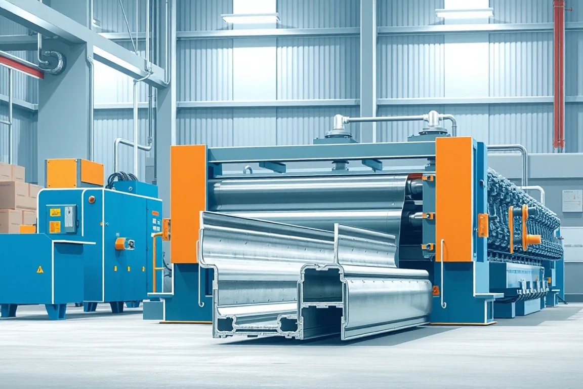
A U channel roll forming machine turns flat metal strip into a continuous open channel with a base and two legs. Despite the apparent simplicity, the machine is only as useful as the accuracy with which the finished profile is defined. Leg height, internal width, corner radii, base flatness and the measurement condition all affect how the channel fits into its final assembly. This article explains how to describe the profile, which production steps belong on the line, how tooling alternatives differ, and what to inspect so the equipment matches the parts you actually need.
What the finished U channel really is
A U channel has a base web and two legs turned in the same direction, with no return lips. The open geometry gives good access for tooling but also means the legs can spring or flare when released from the forming stands. For specification, treat the channel as a set of functional features rather than a single width. Identify the internal width at the base, the leg heights, the inside corner radii, the angle between each leg and the base, and any intentional taper. Distinguish between dimensions that mate with another part and dimensions that are visual only. A channel that nests inside a housing may need a controlled internal width, while a channel used as a spacer may only need consistent outside width. The measurement condition matters because the same section can measure differently when free and when restrained. State whether inspection is performed on a free piece or on a fixture that simulates assembly, and keep that condition consistent between first-off and production. Holes, slots, notches, embosses and cutouts are part of the finished profile even though they are not formed by the bending rolls. Each feature must be located from a functional datum so that the cutoff length and the hole pattern stay in the correct relationship.
Interfaces: the hidden dimensions that control fit
Most fit problems on a U channel trace back to an interface that was never explicitly defined. A mating panel may sit against the outside of the base, inside the legs, or over the leg ends. Each case makes a different dimension critical. If the channel receives a cover plate, the internal width and inside corner radii set the clearance. If the channel slides into a rail, the outside width and leg-end condition control the fit. If fasteners pass through the base, the hole position relative to the base edge and the web flatness around the hole determine whether assembly is reliable. Include any required end treatment in the interface description. A square cut end, a deburred end and an end with a punched notch all behave differently in a fixture. When several channel sizes share the same mating interface, identify which dimensions must remain common and which may vary.
Production route from coil to finished part
The typical route is feasibility review, coil preparation, progressive forming, secondary features and cutoff. Feasibility review checks whether the proposed bend radii, leg heights and material can be developed from flat strip without cracking, excessive thinning or uncontrolled distortion. Coil preparation covers decoiling, joining, feeding and sometimes levelling. Progressive forming uses a series of driven roll stands, each making a small increment of the final bend. The number of passes depends on the material, thickness and bend severity; ductile low-carbon steel can often be formed in fewer passes than high-strength or stainless strip. Secondary features include punching, notching, embossing or slotting, which may be performed before forming, between forming passes or after forming, depending on the feature location and tool access. Cutoff separates the finished length, commonly with a die that supports the channel while a blade or shear passes through. The sequence is not arbitrary. A hole placed before forming may distort, while a hole placed after forming may require access that the closed channel does not allow. The process route should be written as a sequence with the reason for each position.
Tooling alternatives: dedicated, adjustable and hybrid
Tooling strategy is one of the most consequential choices on a U channel line. Dedicated tooling is built for one profile and one material condition. It tends to give the most stable forming and the simplest setup, but it offers little flexibility if the channel size changes. Adjustable or range tooling uses movable roll positions, spacers or interchangeable components to cover a family of widths or leg heights. It can reduce the cost of adding a size, but the adjustment range is always bounded, and each new size still needs verification. Hybrid arrangements combine dedicated forming for critical bends with adjustable elements for non-critical dimensions. The choice depends on the batch mix, not on the largest nominal channel. A line that will run one size continuously favors dedicated tooling. A line that runs many sizes in small batches may benefit from adjustable tooling, provided the changeover procedure is documented and repeatable. Ask which dimensions can be adjusted, which require new rolls, and whether cutoff and feature tooling must also change. The cheapest initial arrangement can become expensive if later product changes require new stands or a new cutoff die.
Secondary operations and their place in the line
Punching, notching, slotting and embossing are often described as add-ons, but they determine whether the line produces a finished part or only a formed channel. In-line operations keep the part in one setup and reduce handling, but they add tooling cost and can constrain the forming sequence. Off-line operations, such as separate punching after cutoff, may be simpler to tool but add labor, work-in-progress and the risk of losing registration between the formed section and the feature. The right choice depends on feature tolerance, production volume and whether the feature can be made reliably while the strip is flat. A hole pattern that must be located from a formed edge is usually better made after forming, while a simple hole in the base may be made in the flat strip. Deburring, end finishing and any assembly operations should be listed separately so that the equipment scope matches the finished part definition.
Changeover: setup steps, scrap and repeatability
Changeover is not a single action. It may include changing rolls or spacers, adjusting roll positions, replacing punch dies, changing cutoff tooling and adjusting the feed length. The practical question is how many of those steps are tool-less or quick-release and how many require measurement and trial. Setup scrap is the material consumed before the line produces acceptable parts. A line with a fast steady-state speed can still be uneconomical if each batch requires long setup and produces significant scrap. Document the changeover sequence and record the steps so that setup can be repeated by different operators. When comparing alternatives, estimate setup time and scrap for the actual batch mix rather than the best-case size. A machine that is easy to change over may accept a lower steady-state speed and still deliver more accepted parts per shift.
Inspection and accepted output
Inspection should prioritize functional datums and mating features instead of tolerancing every dimension equally. Measure the channel in the defined free or restrained state and document the method, including the fixture, the reference points and the gauge type. First-off inspection confirms that the setup is correct. A representative steady-production sample confirms that the line holds the profile as the coil runs and as tooling warms. Check the internal width, leg heights, corner radii, base flatness, hole positions and cutoff length. Look for twist, camber and leg flare that may not appear in a short sample. Accepted output should be defined per shift with the actual profile and material, not as a single speed figure. Include the inspection frequency, the sampling method and the disposition of parts that fall outside the agreed limits. If the line is expected to run multiple sizes, define acceptance for each size and for the transitions between them.
How to compare machine and tooling alternatives
Compare alternatives against the real production plan. A dedicated line with a single profile may offer the simplest operation, but it cannot absorb a product change without new tooling. A flexible line may cover several sizes, but its adjustment range and changeover time must be verified on the actual profiles. Consider the material as well. Stainless and high-strength steels may need more forming passes, more robust stands and different roll materials than low-carbon steel. Consider the feature operations. A line that forms but does not punch may require a second machine and additional handling. Consider the cutoff. A profile-supported cutoff generally produces better end quality than an unsupported cut, but it needs tooling matched to the section. Finally, separate engineering, roll tools, punch dies, cutoff tools and future size changes in the quotation so that the initial price can be compared with the total cost of ownership. The cheapest initial arrangement may make later product changes expensive.
Practical checklist before approving a line
- Define the complete cross-section, including leg heights, internal width, corner radii and the measurement condition.
- List functional datums and mating interfaces, and state which dimensions may vary between batches.
- Specify the material, thickness and grade, and note any incoming strip variation that must be tolerated.
- Confirm that the proposed bend development is feasible for the material and radii without cracking or excessive thinning.
- Decide which secondary features are made in-line and which are made off-line, and justify each choice.
- Confirm cutoff requirements, including cut length, end quality and any secondary operations at the ends.
- Ask which dimensions are adjustable and which require new tools, including cutoff and feature tooling.
- Document the changeover sequence and estimate setup time and setup scrap for the actual batch mix.
- Define accepted output per shift with the actual profile and material.
- Run the agreed material and profile, inspect first-off and steady-production samples, and record the results.
- Separate engineering, tooling, and future size changes in the quotation.
FAQ
Can one U channel roll forming machine produce several channel sizes?
It can, if the tooling is designed as a range or adjustable set and if the machine has enough stands and adjustment points. The practical limit is set by which dimensions can be adjusted without losing forming stability. Internal width, leg height and corner radii may each need separate adjustment. Ask which dimensions are adjustable and which require new rolls, then verify the changeover on the actual profiles.
Why does the measurement condition matter for a U channel?
An open channel can spring or flare when it leaves the forming stands. A free piece may measure differently from a restrained piece that simulates its position in an assembly. If the drawing does not state the condition, two parties can measure the same part and disagree. Define the condition, the fixture and the reference points, and use the same method for first-off and production inspection.
Should holes be punched before or after forming?
It depends on where the hole is and what it must align with. Holes in the flat base may be punched before forming, but they can distort as the section bends. Holes located from a formed edge or a leg are often better made after forming, when the reference surface exists. Tool access, feature tolerance and production volume all influence the decision.
What causes leg flare or twist in a formed U channel?
Leg flare and twist usually come from insufficient forming passes, uneven roll pressure, poor strip guidance or material with inconsistent properties. They can also result from a bend development that asks the material to stretch more than it can tolerate. The fix may be more passes, revised roll geometry or a different material condition. Inspection should include these defects because they affect mating fit even when the base width is correct.
How should cutoff requirements be described?
Describe the cut length, the tolerance, the end condition and any secondary operation at the end. State whether the cut must be square, deburred or notched, and whether the profile needs internal support during cutting. A profile-supported cutoff generally gives better end quality, but the tooling must match the section. Include the cutoff in the acceptance sample so that end quality is verified with the profile.
What should be included in accepted output per shift?
Accepted output should be defined with the actual profile and material, and it should account for setup, scrap and any secondary operations. Include the inspection frequency, the sampling method and the disposition of nonconforming parts. A single speed figure is not enough because it does not reflect changeover, feature operations or the proportion of parts that meet the agreed limits.

Continue your research
- Custom & Industrial Profile Roll Forming Machines
- Custom Profile Roll Forming Machine
- Hat Channel Roll Forming Machine
- C Channel Production Line
- Z Channel Production Line
- Electrical Cabinet Frame Roll Forming Machine
- How Custom profile roll forming machine Works
- How To Choose a Custom profile roll forming machine
- Custom profile roll forming machine Price: What Affects the Cost?
Configuration & specification inputs
Match the configuration to your section drawing, material and production requirements.
| Parameter | Requirement / confirmation needed |
|---|---|
| Profile geometry | A U channel is open and unlipped, but that simplicity does not make all sizes interchangeable. Specify leg heights, internal width, corner radii and the measurement condition. |
| Material | Specified steel, stainless steel or nonferrous strip after feasibility review |
| Thickness & grade | Buyer to specify base-metal thickness and grade; operating range requires supplier verification. |
| Process route | Feasibility review → coil preparation → progressive forming → secondary features → cutoff |
| Cutting | Confirm profile-supported cutoff, cut lengths, end quality and any secondary operations. |
| Output | Define accepted output per shift with the actual profile and material. |
| Electrical supply | Buyer to state voltage / frequency / phase. Installed power requires a confirmed equipment schedule. |
| Acceptance | For a range of channel sizes, ask which dimensions can be adjusted and which require new tools. Include cutoff and feature tooling. Compare setup and accepted output against the actual batch mix rather than the largest nominal channel. |